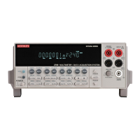
2-28 Close/Open Switching Module Channels Model 2700 Multimeter/Switch System User’s Manual
3. Close channels 1 and 11 to connect DUT #1 to the DMM and bias supply.
Front panel operation: Press CLOSE > Select MULTI > Key in 101 >
Press ENTER
Press CLOSE > Select MULTI > Key in 111 >
Press ENTER
Remote programming: ROUT:MULT:CLOS (@101,111)
4. Measure DUT #1.
Front panel operation: Take reading from display
Remote programming: DATA?
5. Open channels 1 and 11.
Front panel operation: Press OPEN > Select MULTI > Key in 101 >
Press ENTER
Press OPEN > Select MULTI > Key in 111 >
Press ENTER
Remote programming: ROUT:MULT:OPEN (@101,111)
6. Modify steps 3, 4, and 5 to test DUT #2. That is, close channels 2 and 12, measure
DUT #2, and then open channels 2 and 12.
7. Test the remaining eight DUT in a similar manner. That is, close the appropriate
channels for the DUT, make the measurement, and then open the channels.
8. After the last DUT is tested, repeat step 1 to open all channels.
Identifying installed modules and
viewing
closed channels
On power-up, the model numbers of installed switching modules are displayed briefly.
If a Model 7700, 7701, 7702, 7703, 7705, 7708, or 7709 switching module is removed
while the Model 2700 is on, the instrument will operate as if the module is installed. That
is, the Model 2700 will operate as if the pseudocard is installed.
NOTE If a Model 7706 or 7707 is removed while power is on, error +523 “Card
hardware error” will occur, and the module will be removed from the system.
NOTE In general, it is not recommended to install or remove switching modules with
the power on.

 Loading...