8-10 Triggering Model 2700 Multimeter/Switch System User’s Manual
External triggering example
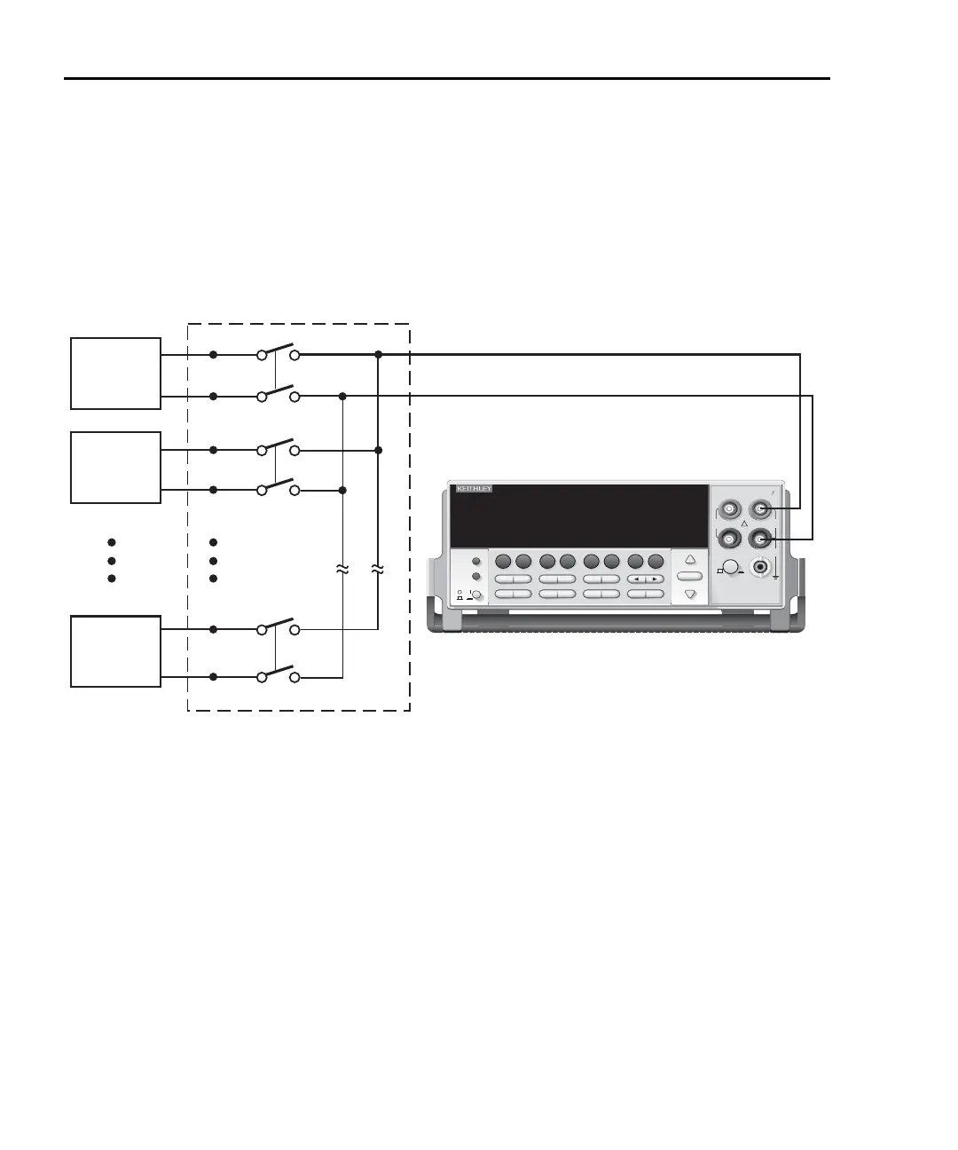
For a test system that requires a large number of switching channels, the Model 2700 can
be used with external scanners such as the Keithley Models 7001 and 7002. For example,
10 Model 7011s installed in the Model 7002 can provide up to 400 2-pole channels, as
shown in
Figure 8-6.
Figure 8-6
DUT test system
The Trigger Link connections for this test system are shown in Figure 8-7. Trigger Link of
the Model 2700 is connected to Trigger Link (either IN or OUT) of the Model 7002. Note
that with the default trigger settings on the Model 7002, line #1 is an input and line #2 is
an output. This complements the trigger lines on the Model 2700.
F
!
F
Model 2700 Multimeter / Data Acquisition System
RANGE
F
500V
PEAK
FRONT/REAR
3A 250V
AMPS
HI
INPUT
LO
SENSE
Ω 4 WIRE
INPUTS
350V
PEAK
1000V
PEAK
AUTO
SHIFT
LOCAL
POWER
RANGE
R
EXIT ENTER
DIGITS RATE
RELFILTER
TRIG
EX TRIG
STORE
RECALL
OPEN
DCV
DCI
MATH
OUTPUT
RATIO
ACV
ACI
Ω2 Ω4
FREQ
TEMP
CH AVG
CONT
PERIOD SENSOR
LIMITS ON/OFFDELAY
HOLD
SAVE SETUP
CONFIG HALT
TYPE
LSYNC
TEST
MONITOR
STEP SCAN
OCOMP
CH-OFF
CARD
CLOSE
Integra Series
RS-232
GPIB
DUT
#1
DUT
#400
DUT
#2
OUTPUT
Card 1
1
2
400
10 7011 MUX Cards
Model 2700

 Loading...


