1-14 Getting Started Model 2700 Multimeter/Switch System User’s Manual
Rear panel summary
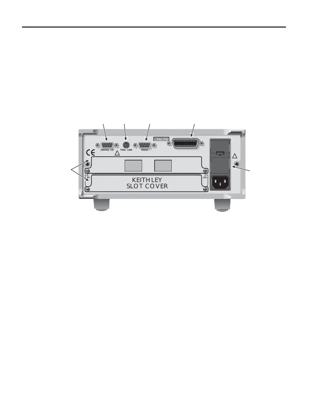
The rear panel of Model 2700 is shown in Figure 1-2. As shown, a slot cover is installed
on slot 2.
WARNING Slot covers must be installed on unused slots to prevent personal
contact with high voltage circuits.
Figure 1-2
Model 2700 rear panel
1 DIGITAL I/O
Male DB-9 connector for digital input (trigger link in) and digital outputs.
2 TRIG LINK
Eight-pin micro-DIN connector for sending and receiving trigger pulses among connected instruments.
Use a trigger link cable or adapter, such as Models 8501-1, 8501-2, 8502, and 8503.
3 RS-232
Female DB-9 connector for RS-232 operation. Use a straight-through (not null modem) DB-9 shielded
cable.
4 IEEE-488
Connector for IEEE-488 (GPIB) operation. Use a shielded cable, such as Models 7007-1 and 7007-2.
5 Power module
Contains the AC line receptacle, power line fuse, and line voltage setting. The instrument can be
configured for line voltages of 100V/120V/220V/240VAC at line frequencies of 50 or 60Hz.
6 Slot 1 and Slot 2
Two slots to accommodate Keithley Model 77xx series switching modules. The Model 2700 is shipped
from the factory with slot covers installed. Please note additional slot covers can be requested from
Keithley Instruments.
WARNING Slot covers must be installed on unused slots to prevent personal
contact with high voltage circuits.
1
2
3
4
5
6
KEITHLEY
SLOT COVER
DIGITAL I/O TRIG. LINK
RS232
WARNING:NO INTERNAL OPERATOR SERVICABLE PARTS,SERVICE BY QUALIFIED PERSONNEL ONLY.
CAUTION:FOR CONTINUED PROTECTION AGAINST FIRE HAZARD,REPLACE FUSE WITH SAME TYPE AND RATING.
MADE IN
U.S.A.
!
!
IEEE-488
SLT
2
SLT
1

 Loading...


