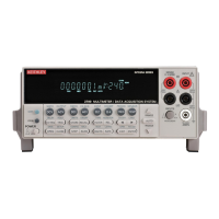
Model 2700 Multimeter/Switch System User’s Manual Getting Started 1-13
MATH mX+b, percent, or reciprocal (1/X) calculation enabled.
MED Medium reading rate selected.
MON Monitor channel displayed.
OCOMP 4-wire offset compensated ohms enabled.
RATIO Channel ratio enabled.
REAR Front panel input terminals disconnected.
REL Relative enabled for selected function.
REM Instrument in GPIB remote mode.
SCAN Scanning operation being performed.
SHIFT Accessing a shifted key.
SLOW Slow reading rate selected.
SRQ Service request over GPIB.
STAT Displaying buffer statistics.
STEP Stepping operation being performed.
TALK Instrument addressed to talk over GPIB bus.
TIMER Timer controlled triggering in use.
TRIG External triggering selected (trigger link, TRIG key, or GPIB).
5 INPUTS switch:
Use to select front panel inputs (out; F) position, or switching module inputs (in; R) position.
NOTE For remote programming, the following command queries the INPUTS switch
position:
SYSTem:FRSWitch? ' Query INPUTS switch; 0 = rear, 1 = front.
6 Handle:
Pull out and rotate to desired position.
7 Front panel inputs:
INPUT HI and LO Used for DCV, ACV, Ω2, CONT, FREQ, PERIOD, and thermocouple/thermistor
TEMP measurements.
SENSE HI and LO Use with INPUT HI and LO for Ω4 and RTD TEMP measurements.
AMPS Use with INPUT LO for DCI and ACI measurements.
Amps fuse holder Holds current fuse for front panel amps input.

 Loading...