Model 2700 Multimeter/Switch System User’s Manual Getting Started 1-15
Power-up
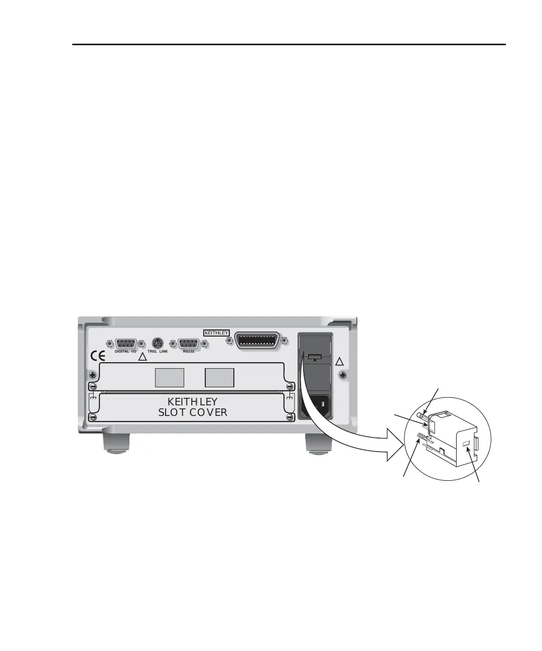
Line power connection
Follow the procedure below to connect the Model 2700 to line power and turn on the
instrument.
1. Check to see that the line voltage indicated in the window of the fuse holder
assembly (
Figure 1-3) is correct for the operating voltage in your area. If not, refer
to “Setting line voltage and replacing fuse,” page 1-16.
CAUTION Operating the instrument on an incorrect line voltage may cause
damage to the instrument, possibly voiding the warranty.
2. Before plugging in the power cord, make sure that the front panel power switch is
in the off (O) position.
Figure 1-3
Power module
Model 2700
KEITHLEY
SLOT COVER
DIGITAL I/O TRIG. LINK
RS232
WARNING:NO INTERNAL OPERATOR SERVICABLE PARTS,SERVICE BY QUALIFIED PERSONNEL ONLY.
CAUTION:FOR CONTINUED PROTECTION AGAINST FIRE HAZARD,REPLACE FUSE WITH SAME TYPE AND RATING.
MADE IN
U.S.A.
!
!
IEEE-488
SLT
2
SLT
1
Fuse
Spring
Window
Line
Voltage
Selector
Fuse Holder Assembly
120
240
220
100

 Loading...


