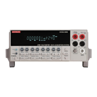
1-26 Getting Started Model 2700 Multimeter/Switch System User’s Manual
Remote programming information
Remote programming information is integrated with front panel operation throughout this
manual. Programming commands are listed in tables, and additional information that
pertains exclusively to remote operation is provided after each table. The tables may
reference you to other sections of this manual.
NOTE Except for Sections 11 through 15, most programming tables in this manual are
abridged. That is, they exclude most optional command words and query
commands. Optional command words and query commands are summarized as
follows.
Optional command words — In order to be in conformance with the IEEE-488.2
standard, Model 2700 accepts optional command words. Any command word that is
enclosed in brackets ([]) is optional and does not have to be included in the program
message.
Query commands — Most command words have a query form. A query command is
identified by the question mark (?) that follows the command word. A query command
requests (queries) the programmed status of that command. When a query command is
sent and Model
2700 is addressed to talk, the response message is sent to the computer.
NOTE For complete details, see “Programming syntax,” page 10-11.
Quick start exercises
This section topic summarizes the following basic instrument operations and provides
simple exercises to perform them:
• Basic DMM measurements — front panel inputs.
• Closing and opening channels — system channel operation.
• Simple scanning.
• Trigger and return readings — remote programming.
WARNING For the exercises, it is not necessary to connect an input signal or DUT
to the instrument (front panel inputs or switching module inputs).
However, if you decide to use an input signal, it is recommended that
you keep it at a nonhazardous level (<42V) while learning to use the
instrument.
NOTE When using the front panel input terminals, the INPUT switch must be in the
“F” (out) position. The INPUT switch is located on the right side of the front
panel near the input terminals. When using a switching module, the switch must
be in the “R” (in) position.

 Loading...