9-6 Limits and Digital I/O Model 2700 Multimeter/Switch System User’s Manual
Digital outputs
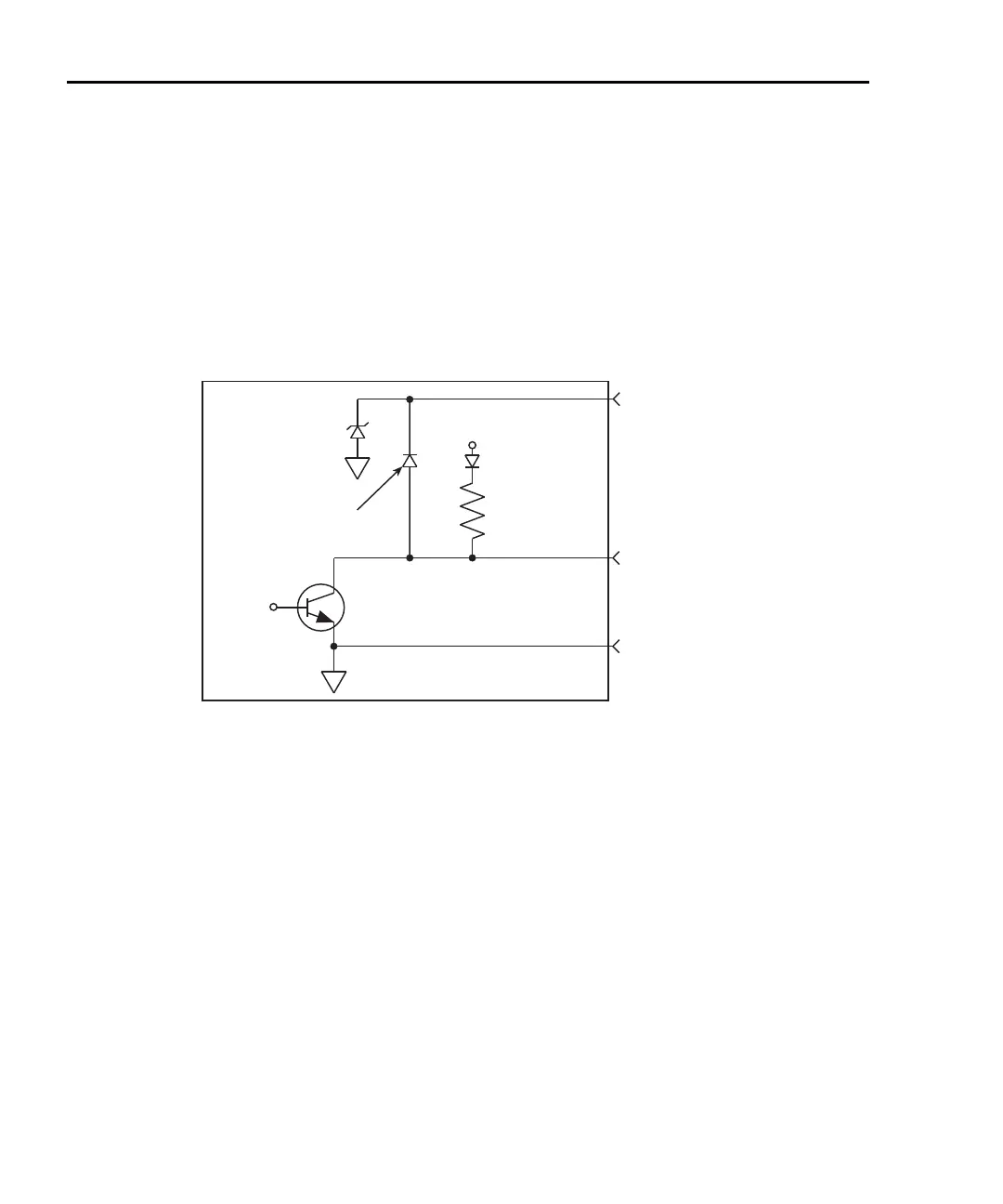
The digital I/O port has five digital outputs. Each digital output can be used as a sink to
control devices (e.g., relays), or as a source to provide input to external logic (TTL or
CMOS) circuitry. The simplified schematic for the digital outputs are shown in
Figure 9-3.
Note that this illustration shows the schematic for one digital output. All five digital output
circuits are identical.
Figure 9-3
Digital I/O port simplified schematic
The five digital output lines (pins 1 through 5) are controlled by limit operations. Each of
these five outputs correspond to the following limit operations:
Digital Output 1 - Low Limit 1 (LO1)
Digital Output 2 - High Limit 1 (HI1)
Digital Output 3 - Low Limit (LO2)
Digital Output 4 - High Limit 2 (HI2)
Digital Output 5 - Master Limit (logical OR of the four above limits)
+5V
4.75k
(Pull-up)
Pin 9 - Digital Ground
Digital Output
Pin 7 (+5V to +33V)
Digital Output
Flyback Diode
Control
Line
33V
Model 2700

 Loading...


