EasyManuals Logo

Keithley 2700 User Manual

Keithley 2700
500 pages
To Next Page IconTo Next Page
To Previous Page IconTo Previous Page
Page #259 background imageLoading...
Page #259 background image
8-8 Triggering Model 2700 Multimeter/Switch System User’s Manual
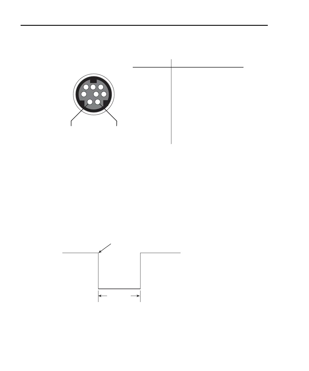
Figure 8-3
TRIG LINK pinout
External trigger
The EXT TRIG input requires a falling-edge, TTL-compatible pulse with the
specifications shown in
Figure 8-4. In general, external triggers can be used to control
measure operations. For the Model 2700 to respond to external triggers, the trigger model
must be configured for it.
Figure 8-4
Trigger link input pulse specifications (EXT TRIG)
TRIG LINK
Pinout
1
2
34
5
6
7
8
Pin 2
External
Trigger
Input
Pin 1
Voltmeter
Complete
Output
Pin Number
1
2
3
4
5
6
7
8
Description
Voltmeter Complete Output
External Trigger Input
No Connection
No Connection
No Connection
No Connection
Signal Ground
Signal Ground
Triggers on
Leading Edge
TTL High
(2V-5V)
TTL Low
(0.8V)
2μs
Minimum

Table of Contents

Other manuals for Keithley 2700

Questions and Answers:

Question and Answer IconNeed help?

Do you have a question about the Keithley 2700 and is the answer not in the manual?

Keithley 2700 Specifications

General IconGeneral
TypeDigital Multimeter
Measurement FunctionsDC Voltage, AC Voltage, DC Current, AC Current, Resistance, Frequency, Temperature
DC Voltage Range100 mV to 1000 V
AC Voltage Range100 mV to 750 V
Frequency Range3 Hz to 500 kHz
Temperature Range-200°C to +1372°C
DisplayVacuum Fluorescent Display
ConnectivityIEEE-488, RS-232
Channels10
Power Supply100V to 240V AC, 45Hz to 66Hz
DC Current Range10 µA to 3 A
AC Current Range10 µA to 3 A
Temperature MeasurementThermocouple, RTD

Related product manuals