8-14 Triggering Model 2700 Multimeter/Switch System User’s Manual
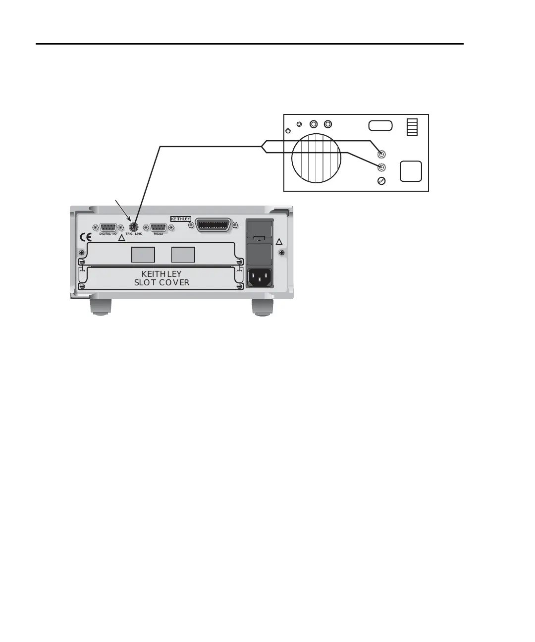
Figure 8-9
DIN to BNC trigger cable
Remote programming — triggering
Trigger model (remote operation)
The following paragraphs describe how the Model 2700 operates for remote operation.
The flow chart in
Figure 8-10 summarizes operation over the bus. The flow chart is called
the trigger model because operation is controlled by SCPI commands from the Trigger
subsystem. Key SCPI commands are included in the trigger model.
Idle and initiate
The instrument is considered to be in the idle state whenever operation is at the top of the
trigger model. As shown in
Figure 8-10, initiation needs to be satisfied to take the
instrument out of idle. While in the idle state, the instrument cannot perform any measure
or step/scan operations.
The following commands will return operation to the top of the trigger model (idle) at the
START point of the trigger model:
•ABORt
• *RCL 0, 1, or 2
•SYSTem:PREset
Model 2700
KEITHLEY
SLOT COVER
DIGITAL I/O TRIG. LINK
RS232
8503 DIN to
BNC Trigger Cable
INPUT
OUTPUT
Model 220 Current Source
External
Trigger
WARNING:NO INTERNAL OPERATOR SERVICABLE PARTS,SERVICE BY QUALIFIED PERSONNEL ONLY.
CAUTION:FOR CONTINUED PROTECTION AGAINST FIRE HAZARD,REPLACE FUSE WITH SAME TYPE AND RATING.
MADE IN
U.S.A.
!
!
IEEE-488
SLT
2
SLT
1
Trigger Link

 Loading...


