3-48 Basic DMM Operation Model 2700 Multimeter/Switch System User’s Manual
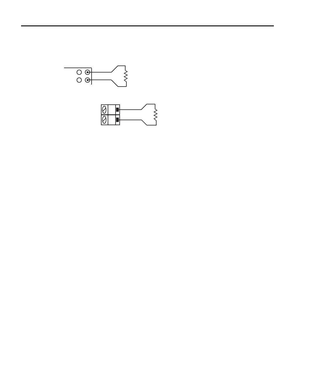
Figure 3-19
Continuity connections
Continuity testing procedure
NOTE Make sure the INPUTS switch is in the correct position. To use front panel
inputs, it must be in the “F” (out) position. For switching modules, it must be in
the “R” (in) position.
1. Apply the resistance to be tested, and, if using a switching module, close the
appropriate channel.
2. Press SHIFT and then CONT to display the present threshold LEVEL.
3. Use , , Δ, and ∇ to key in the desired level (1 to 1000Ω), and press ENTER.
If the measured circuit is below the set threshold level, the instrument will beep and
display the resistance readings.
If the measured circuit is above the threshold level, the instrument will not beep
and either display the resistance reading or the message “OPEN”.
If the reading is below 1100Ω, it will be displayed. If the reading is 1100Ω or
above, “OPEN” will instead be displayed.
4. To disable continuity testing, select a different function (i.e., press DCV).
NOTE The beeper can be disabled using the SYSTem:BEEPer:STATe OFF command.
However, the beeper will automatically enable the next time the continuity
testing function is selected.
Limits and digital outputs cannot be used when testing continuity with the
continuity (CONT) function. If you need to use these operations, use the Ω2
function to test continuity.
H
L
CH 1-20
Model 7700
Switching
Module
Resistance
Under Test
Note: Source current flows from input high to input low.
Model 2700
Input HI
Input LO
Resistance
Under Test
A. Front panel connections
B. Model 7700 connections

 Loading...


