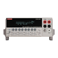
Model 2700 Multimeter/Switch System User’s Manual Getting Started 1-7
The Model 2700 has two slots that will accommodate Keithley Model 7700 series
switching modules (
Table 1-1). Each channel of a switching module that is closed or
scanned is measured by the Model 2700. For scanning, each channel can have its own
unique setup (i.e., function, range, digits, etc.).
More information on the measurement capabilities of the Model 2700 is provided in
“DMM measurement capabilities,” page 3-2. A connection guide for the Model 7700 is
provided in Appendix B. Specifications for the Model 2700 and 7700 switching module
are provided in Appendix A.
Additional features of Model 2700 include:
• Setup storage — Six instrument setups (four user, *RST defaults and factory
defaults) can be saved and recalled.
• Offset-compensated ohms — A two-measurement process for 4-wire ohms to
cancel the effects of thermal EMFs. Available for the 100Ω, 1kΩ
, and 10kΩ ranges.
• Math — mX+b, percent, and reciprocal (1/X) calculations provide mathematical
manipulation of readings.
• Relative — Null offsets or establish baseline values.
• Ratio and channel average — Ratio and average calculations for two switching
module channels.
• Buffer — Store up to 55,000 readings in the internal buffer.
• Limits — Two sets of high and low reading limits to test devices.
• Digital I/O port — Five digital limit test output lines to control external circuitry.
The trigger link and hardware interlock input can also be accessed at this port.
• Monitor — The Model 2700 can monitor a selected channel. A scan can be
triggered to start when the Monitor detects a reached reading limit.
• Remote interface — Model 2700 can be controlled using the IEEE-488 interface
(GPIB) or the RS-232 interface.
Plug-in switching modules
Up to two Keithley Model 77xx series switching modules can be installed in the
Model
2700. A side-by-side comparison of the switching modules is provided in
Table 1-1.
Basic close/open operation for switching module channels is provided in Section 2, while
scanning is covered in Section 7. Connection information for the Model 7700 switching
module is provided in Appendix B. For all other switching modules, connection
information is provided in their respective packing lists.

 Loading...