8-4 Triggering Model 2700 Multimeter/Switch System User’s Manual
Delay (auto or manual)
A programmable delay is available after event detection. It can be set manually or an auto
delay can be used. With auto delay selected, the instrument automatically selects a delay
period that will provide sufficient settling for function and autorange changes and multi-
phase measurements.
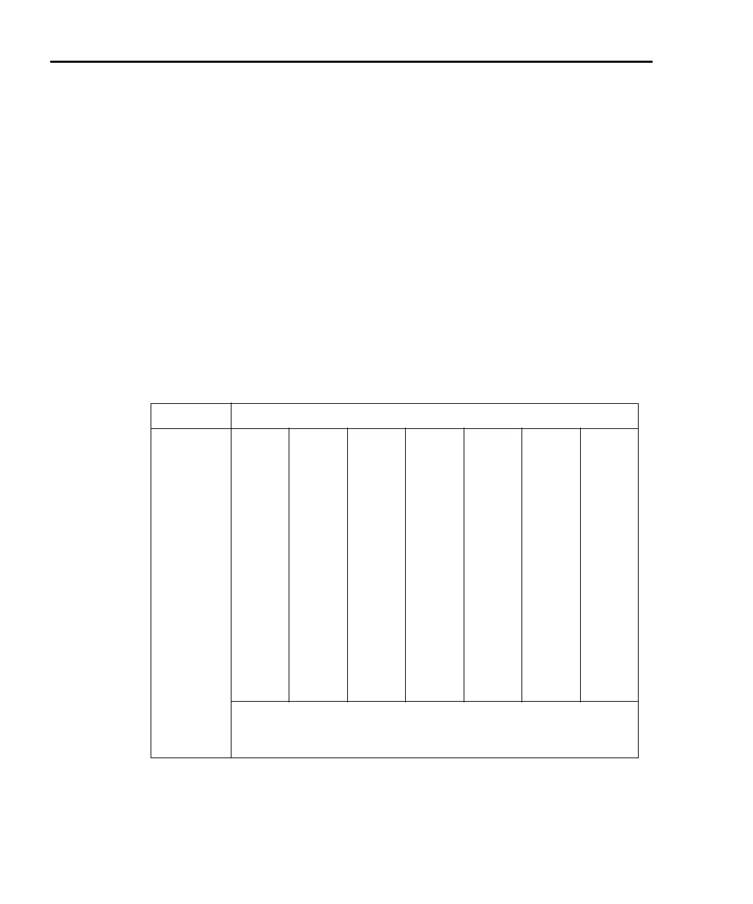
Normal measurement state — With auto delay selected and the External or Bus control
source selected, the Model 2700 selects a delay based on the selected voltage range. The
auto delay period cannot be adjusted by the user. The auto delays are listed in
Table 8-1.
With one of the other control sources selected, the auto delay is 0.000s for all functions
and ranges.
Scanning — When scanning, the nominal delay will be long enough to allow each switch-
ing module channel relay to settle before making the measurement. When scanning, the
auto delay times in
Table 8-1 are valid for all control sources.
The delay function is accessed by pressing SHIFT and then DELAY. The present delay
setting (AUTO or MANual) is displayed. Press the
Δ or ∇ key to display the desired
setting and press ENTER.
Table 8-1
Auto delay settings
Function Range and delay
DCV 100mV
1ms
1V
1ms
10V
1ms
100V
5ms
1000V
5ms
ACV 100mV
400ms
1V
400ms
10V
400ms
100V
400ms
750V
400ms
FREQ and
PERIOD
100mV
1ms
1V
1ms
10V
1ms
100V
1ms
750V
1ms
DCI 20mA
2ms
100mA
2ms
1A
2ms
3A
2ms
ACI 1A
400ms
3A
400ms
Ω2, Ω4 100Ω
3ms
1kΩ
3ms
10kΩ
13ms
100kΩ
25ms
1MΩ
100ms
10MΩ
150ms
100MΩ
250ms
Continuity 1kΩ
3ms
TEMP The auto delay for thermocouples is 1ms. For thermistors and 4-wire
RTDs, the auto delay period is the same as the delay for the resistance
range that is used for the measurement.

 Loading...


