EasyManuals Logo

Keithley 2700 User Manual

Keithley 2700
500 pages
To Next Page IconTo Next Page
To Previous Page IconTo Previous Page
Page #294 background imageLoading...
Page #294 background image
Model 2700 Multimeter/Switch System User’s Manual Remote Operations 10-5
GPIB connections
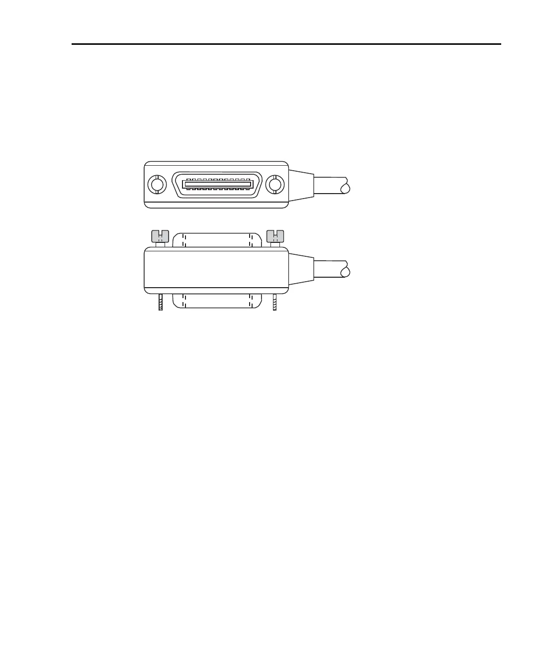
To connect the Model 2700 to the GPIB bus, use a cable equipped with standard IEEE-488
connectors as shown in
Figure 10-1.
Figure 10-1
IEEE-488 connector
To allow many parallel connections to one instrument, stack the connectors. Two screws
are located on each connector to ensure that connections remain secure. Present standards
call for metric threads, which are identified with dark-colored screws. Earlier versions
have different screws, which are silver-colored. Do not use these types of connectors on
the Model 2700; it is designed for metric threads.

Table of Contents

Other manuals for Keithley 2700

Questions and Answers:

Question and Answer IconNeed help?

Do you have a question about the Keithley 2700 and is the answer not in the manual?

Keithley 2700 Specifications

General IconGeneral
TypeDigital Multimeter
Measurement FunctionsDC Voltage, AC Voltage, DC Current, AC Current, Resistance, Frequency, Temperature
DC Voltage Range100 mV to 1000 V
AC Voltage Range100 mV to 750 V
Frequency Range3 Hz to 500 kHz
Temperature Range-200°C to +1372°C
DisplayVacuum Fluorescent Display
ConnectivityIEEE-488, RS-232
Channels10
Power Supply100V to 240V AC, 45Hz to 66Hz
DC Current Range10 µA to 3 A
AC Current Range10 µA to 3 A
Temperature MeasurementThermocouple, RTD

Related product manuals