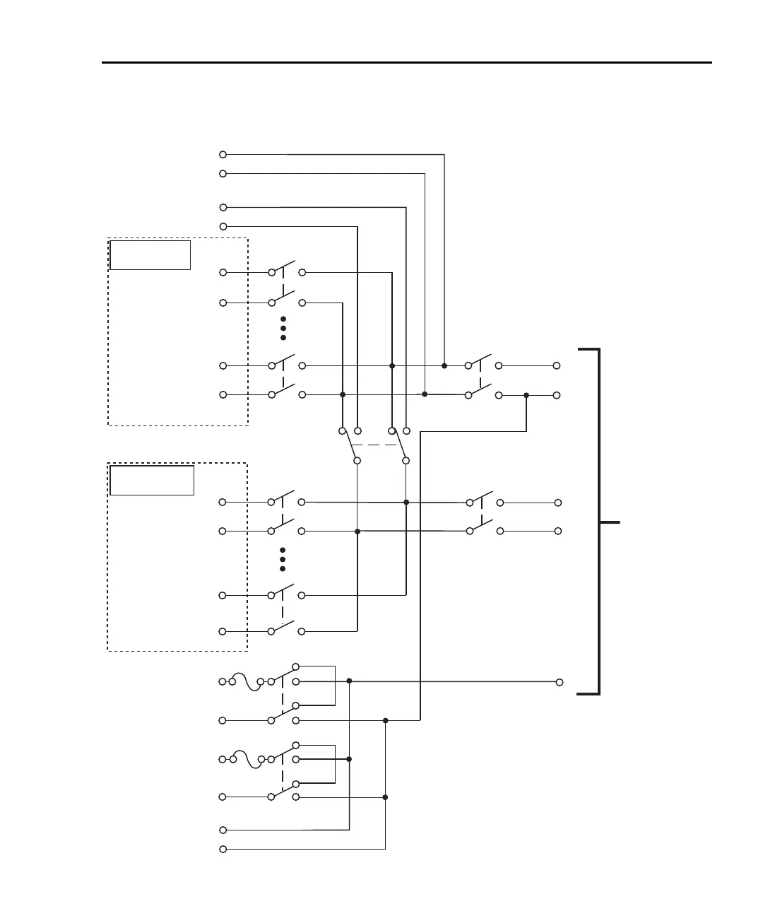
EasyManuals Logo

Keithley 2700 User Manual

Keithley 2700
500 pages
To Next Page IconTo Next Page
To Previous Page IconTo Previous Page
Page #402 background imageLoading...
Page #402 background image
Model 2700 Multimeter/Switch System User’s Manual Model 7700 Connection Guide B-3
Figure B-1
Simplified schematic for Model 7700
Notes:
Cold Junction
Ref x3
Channel 1
HI
LO
Channel 10
HI
LO
(Channels 2–9)
Channel 11
HI
LO
Channel 20
HI
LO
(Channels 12–19)
Channel 21
HI
LO
Channel 22
HI
LO
AMPS
HI
LO
Sense
HI
LO
Input
Channel 23
2-Pole (Open)
4-Pole (Closed)
(See Note)
3A
3A
To
Model 2700
Backplane
Channel 25
(See Note)
Backplane
Isolation
Channel 24
(See Note)
Backplane
Isolation
Channels 23 and 25 in this schematic refer to the
designations used for control and are not actual
available measurement channels.
If the module is not to be internally connected
to the DMM, channels 24 and 25 can be opened
using multiple channel operation (see “Multiple
channel operation” in Section 2 for details).
AMPS
LO
Sense
HI
LO
Input
HI
LO
Cold Junction
Ref x3

Table of Contents

Other manuals for Keithley 2700

Questions and Answers:

Question and Answer IconNeed help?

Do you have a question about the Keithley 2700 and is the answer not in the manual?

Keithley 2700 Specifications

General IconGeneral
TypeDigital Multimeter
Measurement FunctionsDC Voltage, AC Voltage, DC Current, AC Current, Resistance, Frequency, Temperature
DC Voltage Range100 mV to 1000 V
AC Voltage Range100 mV to 750 V
Frequency Range3 Hz to 500 kHz
Temperature Range-200°C to +1372°C
DisplayVacuum Fluorescent Display
ConnectivityIEEE-488, RS-232
Channels10
Power Supply100V to 240V AC, 45Hz to 66Hz
DC Current Range10 µA to 3 A
AC Current Range10 µA to 3 A
Temperature MeasurementThermocouple, RTD

Related product manuals