Keysight N9010A EXA Service Guide 359
Front Panel/Motherboard Troubleshooting
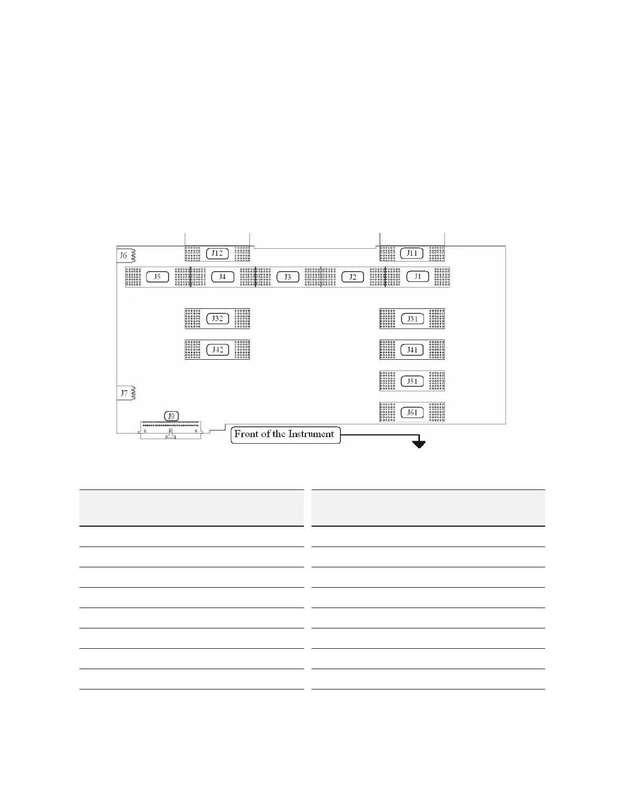
A8 Motherboard Description
The Motherboard is a horizontally mounted, located near the bottom of the
analyzer. The Motherboard has the following connector types:
— (6) Analog Card Cage Connectors (J1, J11, J31, J41, J51, J61)
— (4) Digital Card Cage Signals and voltages using PCI connectors (J4, J12,
J32, J42)
— (1)Analog Power (J2)
— (1) Mixed Power (J3)
— (2) Front Panel Connectors (J5 and J9)
— (2) Fan Connector (J6 and J7)
Figure 11-2 Motherboard Connectors
Motherboard
Connector
What Plugs In? Motherboard
Connector
What Plugs In?
J1 A7, Midplane J11 A3, Digital I.F, analog signals
J2 A7, Midplane J12 A3, Digital I.F, analog signals
J3 A7, Midplane J31 Option Slot
J4 A7, Midplane J32 Option Slot
J5 A7, Midplane J41 Option Slot
J6 B2, Fan #2 J42 Option Slot
J7 B1, Fan #1 J51 A14, L.O. Synthesizer
J9 Front Panel J61 A15, Front End Control

 Loading...


