EasyManuals Logo

Keysight Technologies X Series Service Guide

Keysight Technologies X Series
671 pages
To Next Page IconTo Next Page
To Previous Page IconTo Previous Page
Page #506 background imageLoading...
Page #506 background image
506 Keysight N9010A EXA Service Guide
Assembly Replacement Procedures
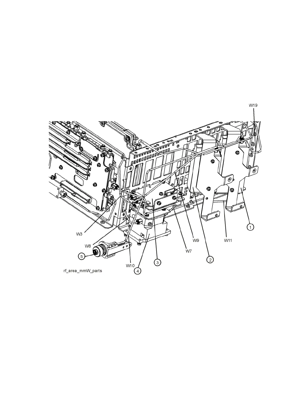
RF Area (Option 532, 544)
Refer to Figure 15-35 and Figure 15-36. The RF area consists of RF attenuator
A (1), RF attenuator B (2), low band switch assembly (3), and YTF
Preselector (4).
Instruments with Options DP2, MPB, or B40 will also have coaxial switch (6),
(Figure 15-36).
Figure 15-35 RF Area Components and Cables - Option 532, 544

Table of Contents

Other manuals for Keysight Technologies X Series

Questions and Answers:

Question and Answer IconNeed help?

Do you have a question about the Keysight Technologies X Series and is the answer not in the manual?

Keysight Technologies X Series Specifications

General IconGeneral
BrandKeysight Technologies
ModelX Series
CategoryMeasuring Instruments
LanguageEnglish

Related product manuals