EasyManuals Logo

Keysight Technologies X Series Service Guide

Keysight Technologies X Series
671 pages
To Next Page IconTo Next Page
To Previous Page IconTo Previous Page
Page #501 background imageLoading...
Page #501 background image
Keysight N9010A EXA Service Guide 501
Assembly Replacement Procedures
RF Area (Option 503, 507, 513, 526)
Attenuators
Removal
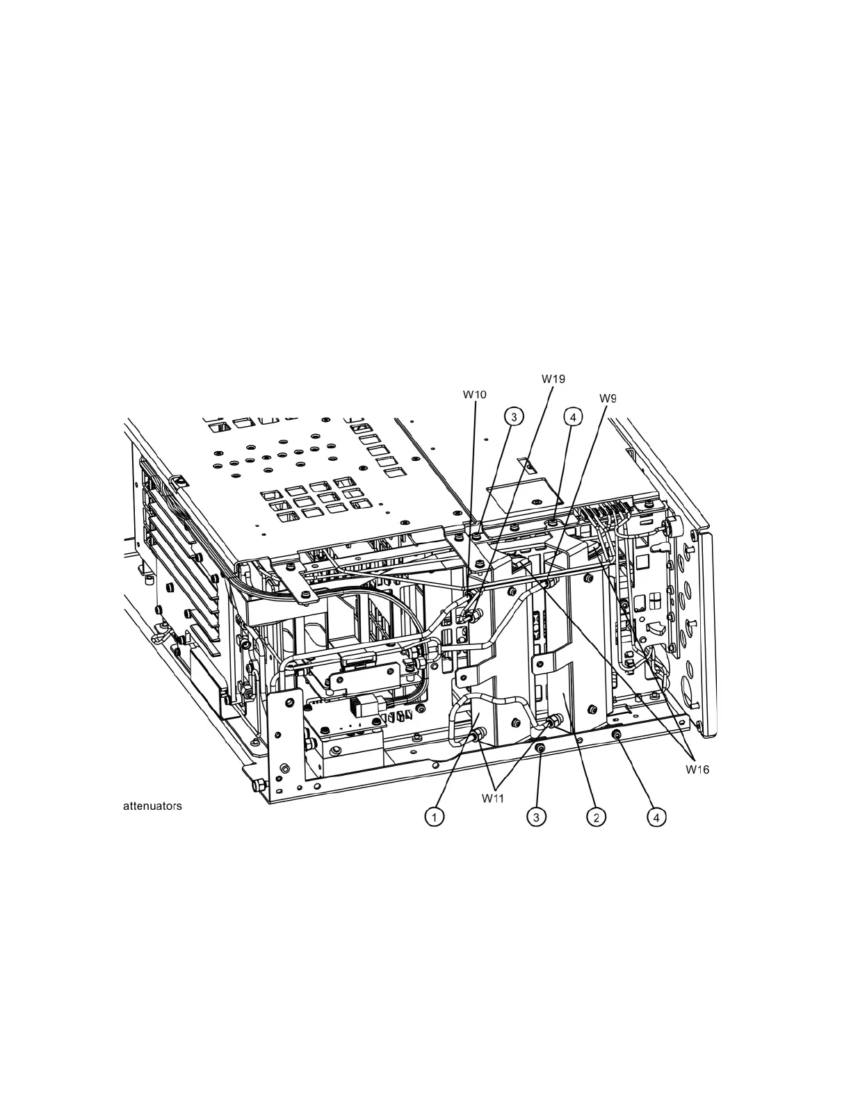
1. Refer to Figure 15-31. To remove Attenuator A (1) or Attenuator B (2),
remove the semi-rigid cables W9, W10, W11 and W19 attached to the
attenuator using the 5/16 inch wrench.
2. Remove the W16 ribbon cable attached to the attenuator.
3. Remove the two screws (3) or (4) for each attenuator bracket to remove
from the chassis using the T-10 driver.
4. Remove the two screws to separate the attenuator from the bracket.
Figure 15-31 Attenuators Removal

Table of Contents

Other manuals for Keysight Technologies X Series

Questions and Answers:

Question and Answer IconNeed help?

Do you have a question about the Keysight Technologies X Series and is the answer not in the manual?

Keysight Technologies X Series Specifications

General IconGeneral
BrandKeysight Technologies
ModelX Series
CategoryMeasuring Instruments
LanguageEnglish

Related product manuals