500 Keysight N9010A EXA Service Guide
Assembly Replacement Procedures
RF Area (Option 503, 507, 513, 526)
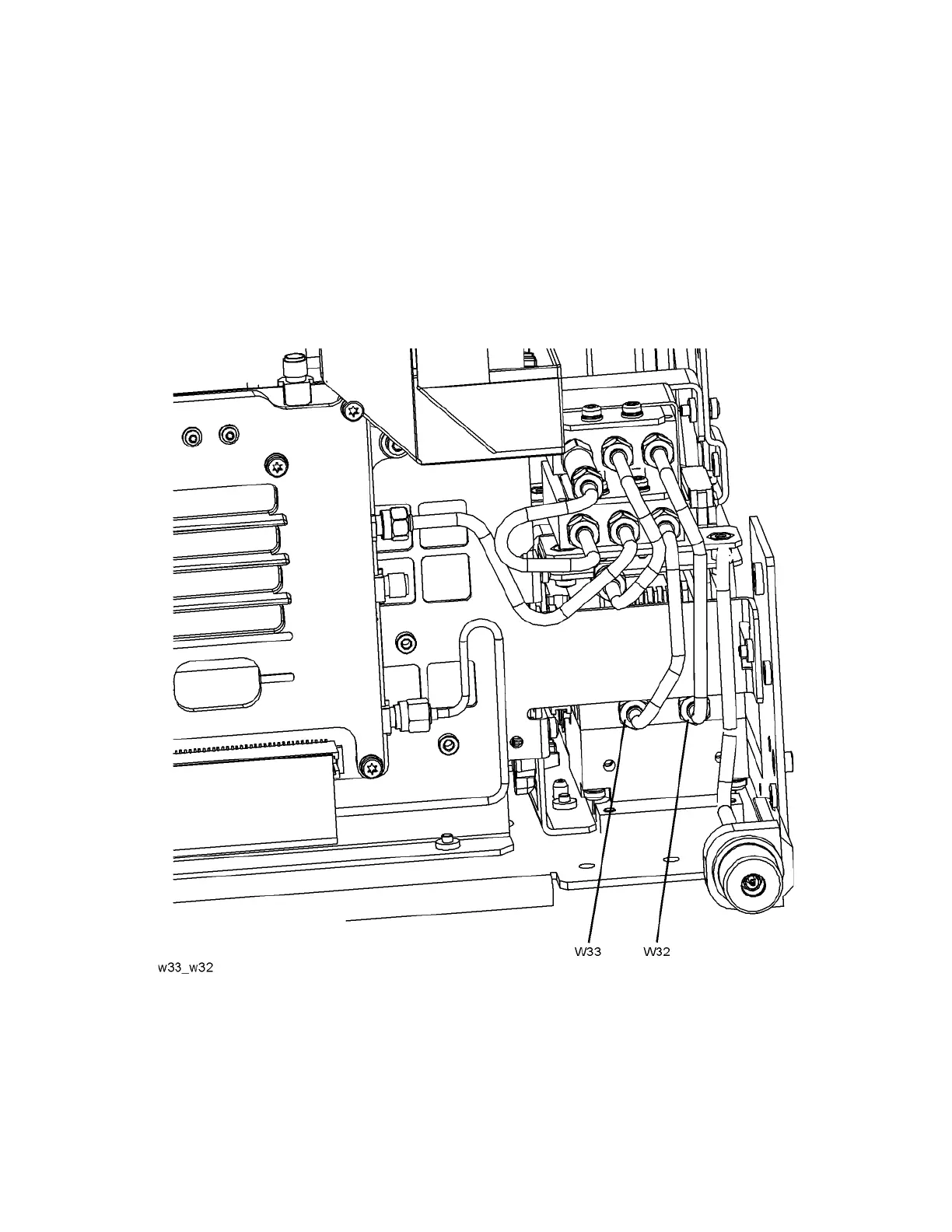
15.Refer to Figure 15-30. Connect W33 semi-rigid coax cable between port 2
of Switch 1 (the lower switch) and the output of the A12 YTF Preselector.
Torque the cable at the A12 end first to 10 inch-pounds and then torque
the cable at the Switch 1 end to 10 inch-pounds.
16.Connect W32 semi-rigid coax cable between port 2 of Switch 2 (the upper
switch) and the input of the A12 YTF Preselector. Torque the cable at the
A12 end first to 10 inch-pounds and then torque the cable at the Switch 2
end to 10 inch-pounds.
Figure 15-30 Install W33 and W32

 Loading...


