Keysight N9010A EXA Service Guide 499
Assembly Replacement Procedures
RF Area (Option 503, 507, 513, 526)
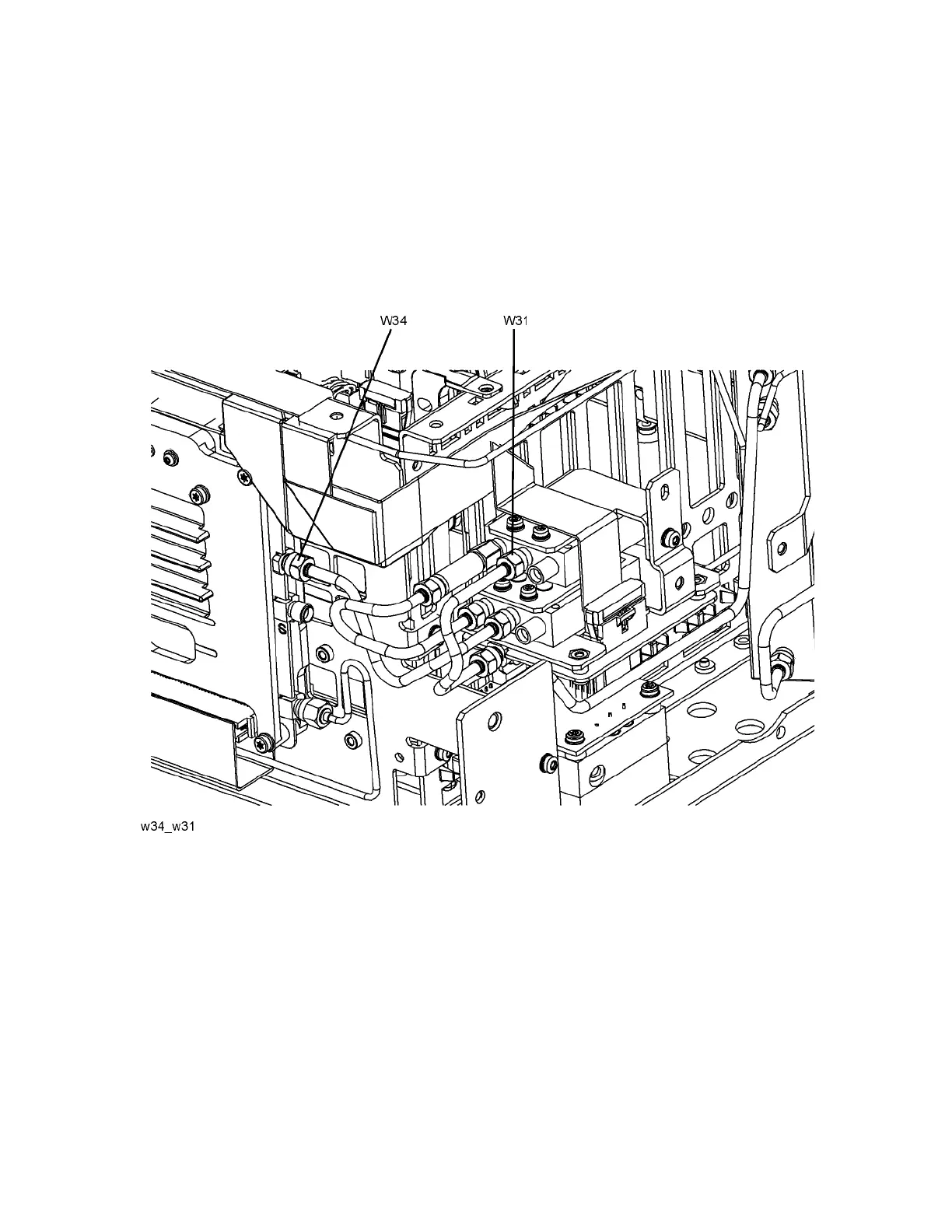
13.Refer to Figure 15-29. Connect W34 semi-rigid coax cable between the
center port of Switch 1 (the lower switch) and J9 of the A13 Front End
Assembly. Torque to 10 inch-pounds.
14.Connect W31 semi-rigid coax cable between the center port of Switch 2
(the upper switch) and J3 of the A11 Low Band Switch. Torque to
10 inch-pounds.
Figure 15-29 Install W34 and W31

 Loading...


