498 Keysight N9010A EXA Service Guide
Assembly Replacement Procedures
RF Area (Option 503, 507, 513, 526)
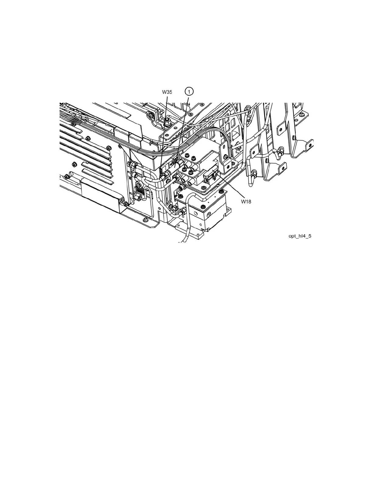
11.Refer to Figure 15-28. Attach the coaxial fixed attenuator (1) Switch 2
port 1. Torque to 10 inch-lbs.
Figure 15-28 Attenuator Installation
12.Connect W35 semi-rigid coax cable between the coaxial fixed attenuator
(1) and port 1 of Switch 1 (the lower switch). Torque to 10 inch-pounds.

 Loading...


