Keysight N9010A EXA Service Guide 497
Assembly Replacement Procedures
RF Area (Option 503, 507, 513, 526)
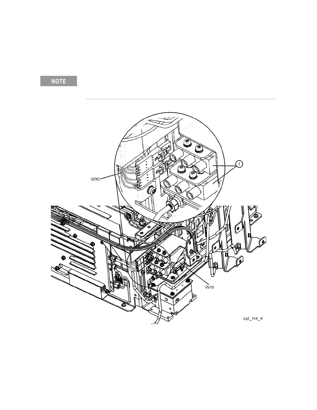
9. Refer to Figure 15-27. Connect the two wire harness connectors W30 to
the switches (1). Once connected, position the connections along side the
switches.
Figure 15-27 Wire Harness Routing
10.Connect ribbon cable W18 to J4 of the A11 Low Band Switch.
Even though the wire colors on W30 harness are different, it does not matter which one plugs
into which switch.

 Loading...


