496 Keysight N9010A EXA Service Guide
Assembly Replacement Procedures
RF Area (Option 503, 507, 513, 526)
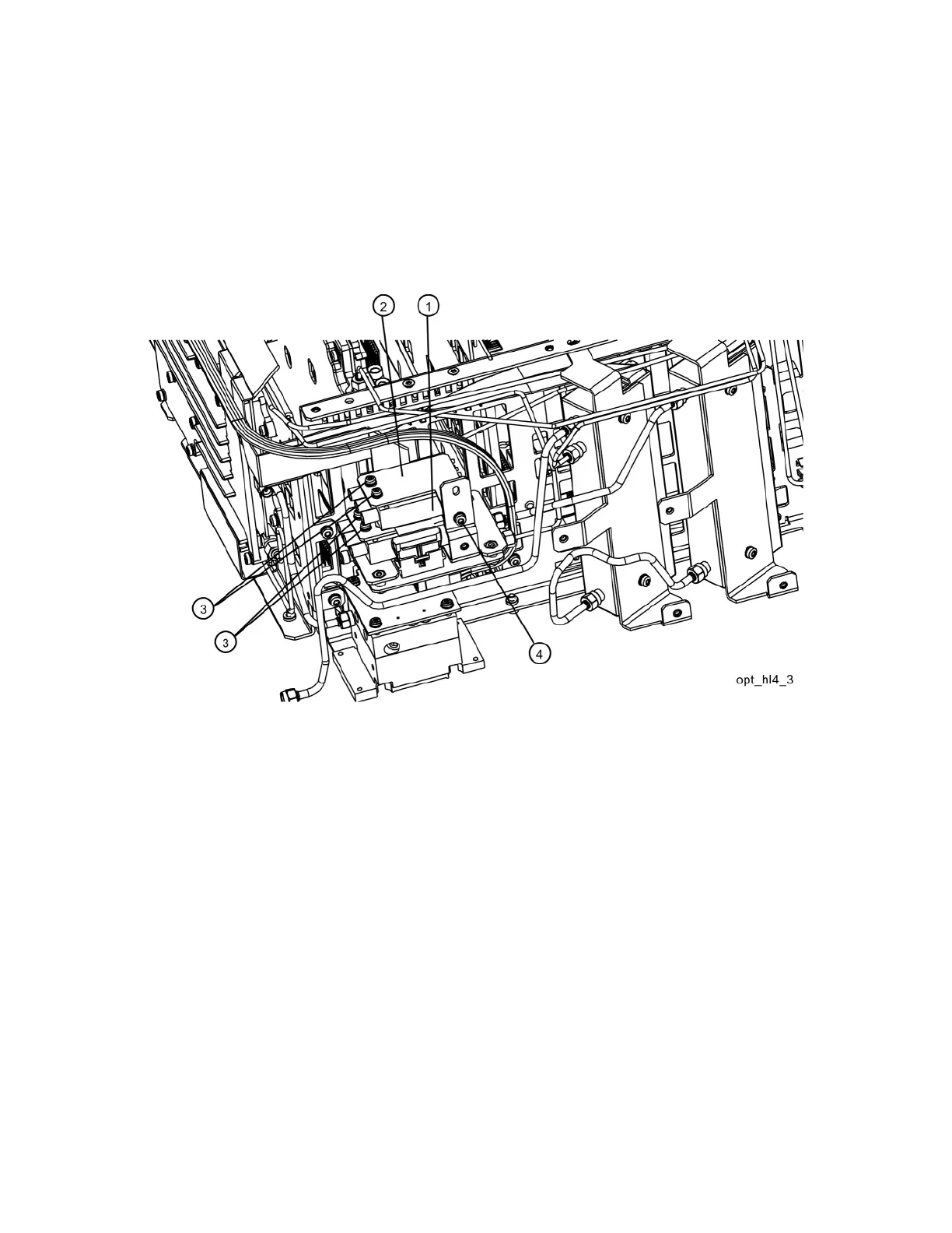
7. Refer to Figure 15-26. Place the second switch/bracket assembly (1)/(2)
on the bracket previously installed. Assure Keysight label on switch is
facing up. Attach the bracket and switch using two 0515-1992 screws (3)
using the T-8 driver. Secure the bracket to the low band switch bracket
with a single screw (4) using the T-10 driver. Do not torque.
Figure 15-26 Switch 2 Placement
8. Align switches so they are parallel with the side of the instrument then
torque the four screws (3) securing the switches to the brackets to
6 inch-pounds using the T-8 driver. Torque the screw (4) that secures the
switch brackets together to 9 inch-pounds using the T-10 driver.

 Loading...


