Keysight N9010A EXA Service Guide 523
Assembly Replacement Procedures
RF Front End Assembly - Options 532, 544
RF Front End Assembly - Options 532, 544
Removal
1. Remove the instrument outer case. Refer to the Instrument Outer Case
removal procedure.
2. Remove the instrument top brace. Refer to the Top Brace and Reference
Bracket removal procedure.
3. Remove the front panel. Refer to the Front Frame Assembly removal
procedure.
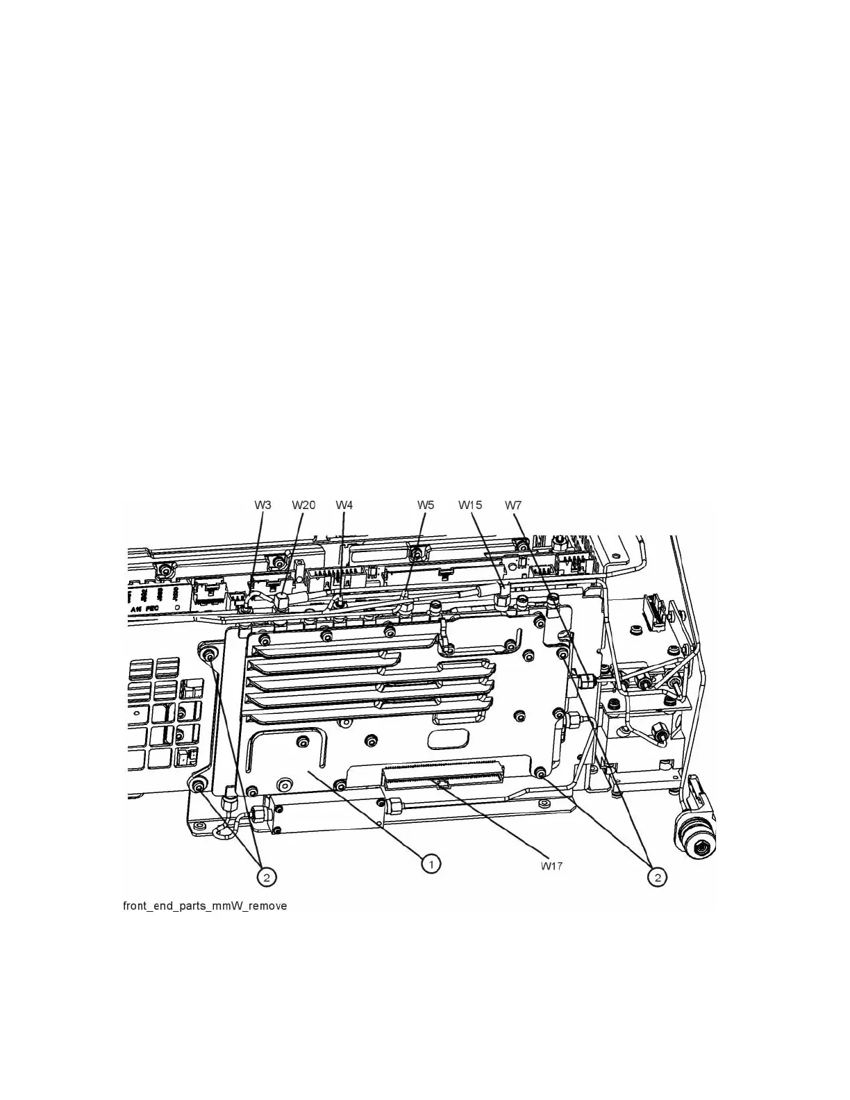
4. Refer to Figure 15-49. Using the 5/16 inch wrench, remove the cables W3,
W4, W5, W7, W15 (or W36), and W20 attached to the RF Front End
Assembly (1).
5. Remove the ribbon cable W17 from the RF Front End Assembly.
6. Remove the four screws (2) using the T-10 driver. The RF Front End
Assembly can now be removed from the chassis.
Figure 15-49 RF Front End Assembly (Option 532, 544) Removal

 Loading...


