EasyManuals Logo

Keysight Technologies X Series Service Guide

Keysight Technologies X Series
671 pages
To Next Page IconTo Next Page
To Previous Page IconTo Previous Page
Page #509 background imageLoading...
Page #509 background image
Keysight N9010A EXA Service Guide 509
Assembly Replacement Procedures
RF Area (Option 532, 544)
Low Band Switch
Removal
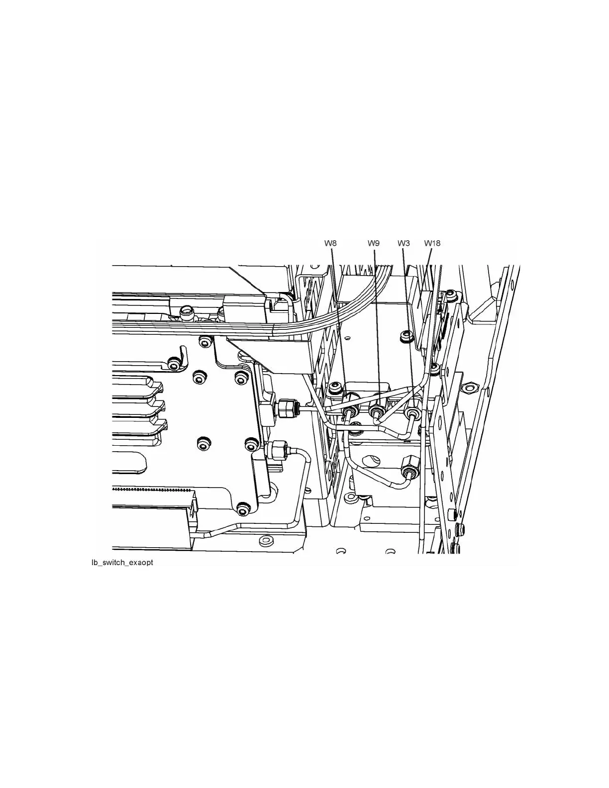
1. Refer to Figure 15-39 and Figure 15-39. Remove the ribbon cable W18.
2. Remove the semi-rigid cables W3, W8, and W9 using the 5/16 inch
wrench.
3. Remove the two screws (2) using the T-10 driver. The low band switch
and bracket (1) can now be removed from the chassis.
Figure 15-38 Low Band Switch Cable Removal

Table of Contents

Other manuals for Keysight Technologies X Series

Questions and Answers:

Question and Answer IconNeed help?

Do you have a question about the Keysight Technologies X Series and is the answer not in the manual?

Keysight Technologies X Series Specifications

General IconGeneral
BrandKeysight Technologies
ModelX Series
CategoryMeasuring Instruments
LanguageEnglish

Related product manuals