530 Keysight N9010A EXA Service Guide
Assembly Replacement Procedures
Rear Panel
Rear Panel
Removal
1. Remove the instrument outer case. Refer to the Instrument Outer Case
removal procedure.
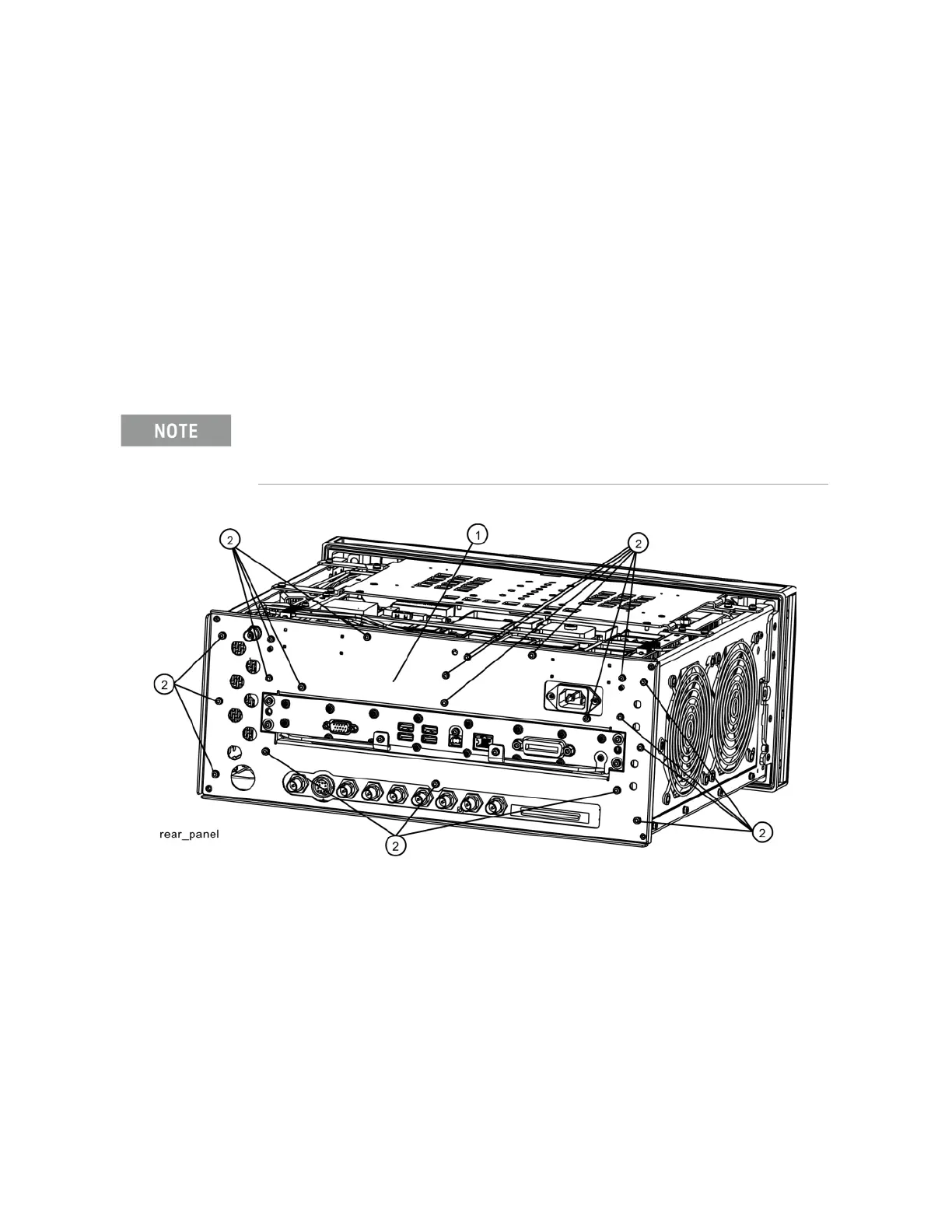
2. Refer to Figure 15-53. Using the T-10 driver, remove the twenty screws
(2) attaching the rear panel (1) to the chassis and to the reference
bracket. The rear panel can now be removed.
3. Refer to Figure 15-54. Remove W23 cable from the A16 Reference
Assembly (1) at A16J704.
Figure 15-53 Rear Panel Removal
Replacement
1. Reattach W23 cable to A16J704 or to the rear panel depending on how
you removed it.
2. Refer to Figure 15-53. Place the rear panel (1) into position in the chassis.
Replace the twenty screws (2) to attach the rear panel to the chassis.
Torque to 9 inch-pounds.
3. Replace the instrument outer case. Refer to the Instrument Outer Case
replacement procedure.
If the rear panel is being replaced with a new rear panel, remove W23 at the rear panel using a
9/16-inch nut driver. Instruments with Option CR3 or CRP will have an additional cable W39
that is attached to the rear panel.

 Loading...


