474 Keysight N9010A EXA Service Guide
Assembly Replacement Procedures
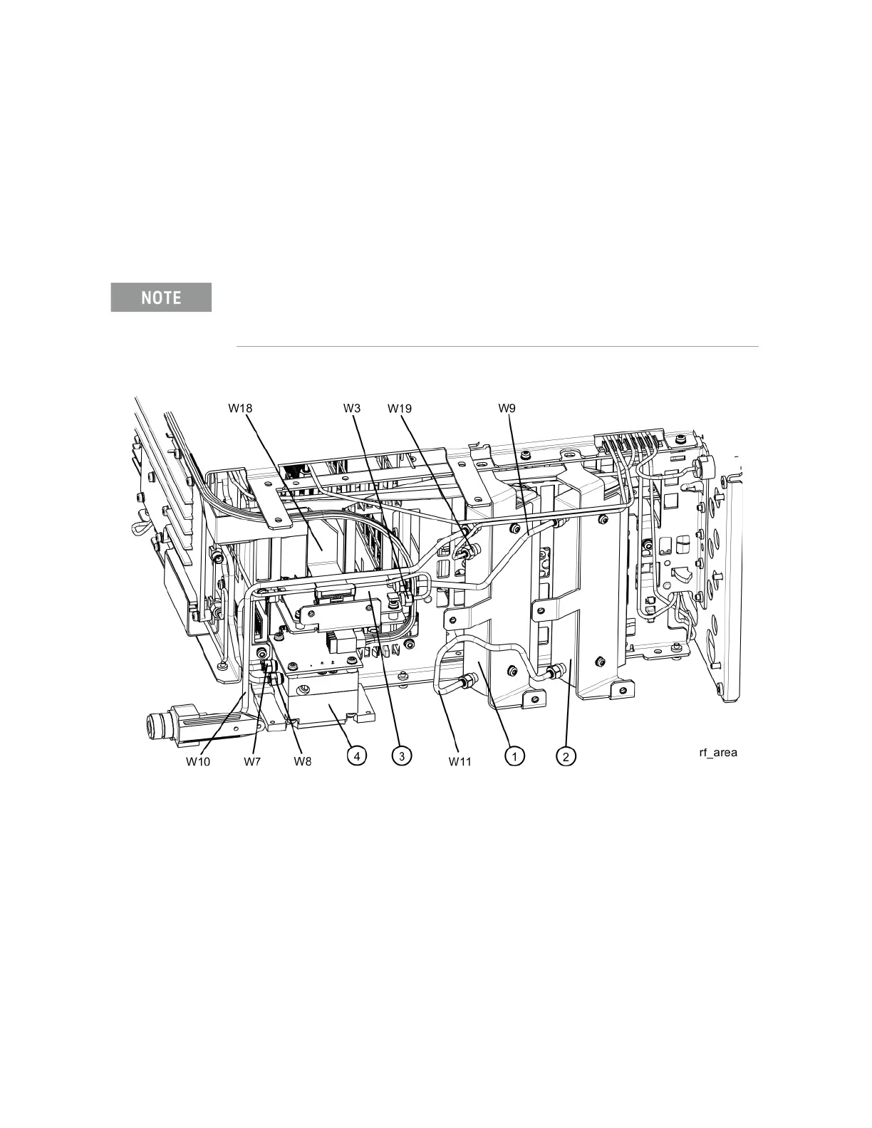
RF Area (Option 503, 507, 513, 526)
RF Area (Option 503, 507, 513, 526)
Refer to Figure 15-7 and Figure 15-8. The RF area consists of RF attenuator A
(1), RF attenuator B (2), low band switch assembly (3), and YTF Preselector
(4).
Instruments with Options DP2, MPB, or B40 will also have coaxial switch #1
(5), coaxial switch #2 (6), and 6 dB fixed attenuator (7) (Figure 15-8).
Figure 15-7 RF Area Components and Cables - Standard Instruments
The YTF Preselector is not typically installed in instruments with Option 503.

 Loading...


