Keysight N9010A EXA Service Guide 553
Assembly Replacement Procedures
Disk Drive
Disk Drive Interconnect
Removal
1. Remove the A5 Disk Drive assembly for the instrument. Refer to the “Disk
Drive” removal procedure.
2. Remove the A4 CPU assembly from the instrument. Refer to the “CPU
Assembly” removal procedure.
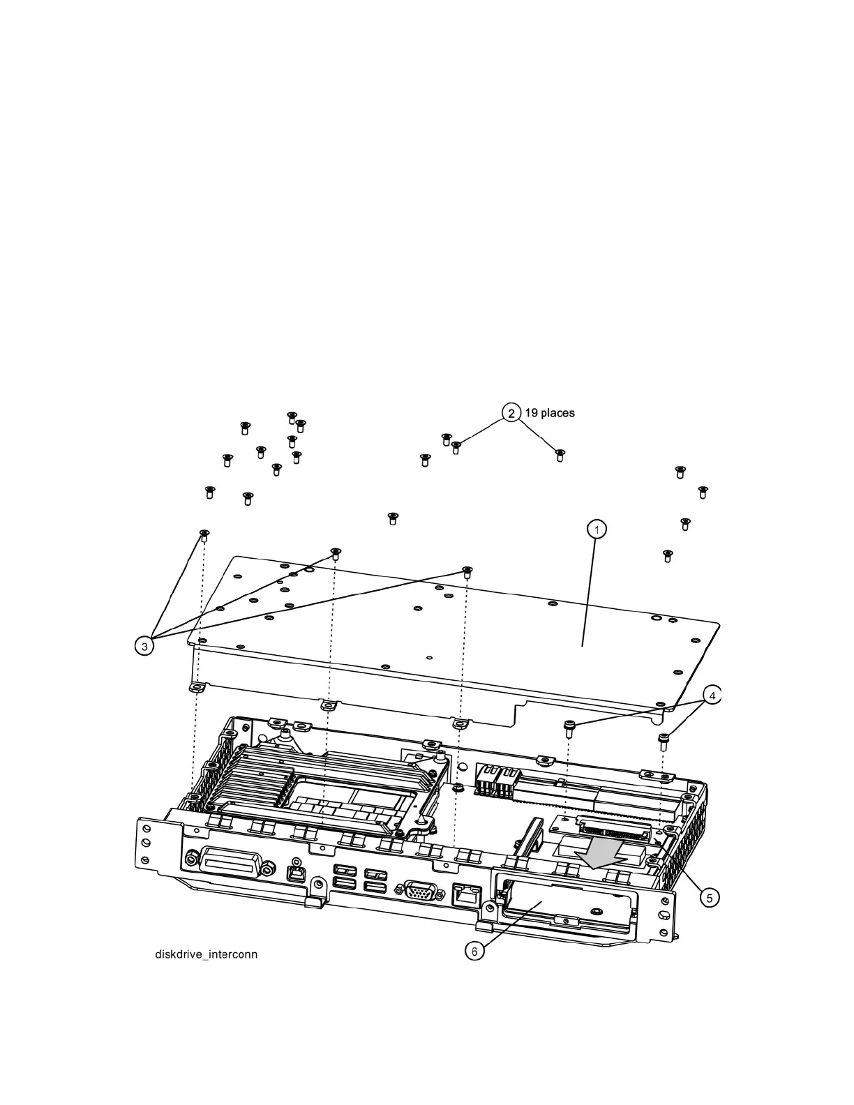
3. Refer to Figure 15-73. Remove the A4 CPU assembly cover (1) by first
removing the 19 flat-head screws (2) and 3 pan-head screws (3). The 19
flat-head screws need to be discarded and replaced since they are
precoated with a thread locking compound and new screws will need to be
used when the cover is re-installed.
Figure 15-73 A4A1 Disk Drive Interconnect Board Removal

 Loading...


