566 Keysight N9010A EXA Service Guide
Assembly Replacement Procedures
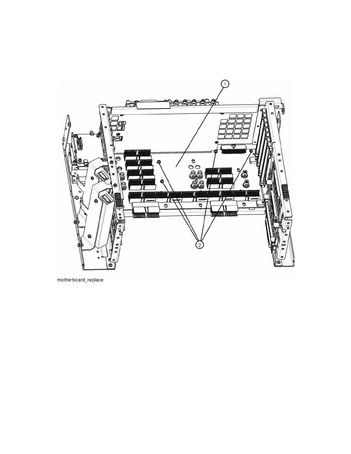
Motherboard Assembly
16.Refer to Figure 15-83. Remove the motherboard (1) by removing the four
screws (2).
Figure 15-83 Motherboard Assembly Removal
Replacement
1. Refer to Figure 15-83. Place the motherboard (1) into position in the
chassis and replace the four screws (2). Torque to 9 inch-pounds.
2. Refer to Figure 15-82. Replace the left side chassis by replacing the seven
screws. Torque to 9 inch-pounds.
3. Refer to Figure 15-80. Replace the midplane bracket (1) by replacing the
eight screws (2). Torque to 9 inch-pounds.
4. Replace the fan assembly. Refer to the Fan Assembly replacement
procedure.
5. Replace the RF bracket. Refer to Figure 15-9 on page 476. Torque the
screws to 9 inch-pounds.

 Loading...


