476 Keysight N9010A EXA Service Guide
Assembly Replacement Procedures
RF Area (Option 503, 507, 513, 526)
To gain access to any of these parts, follow these steps:
1. Remove the instrument outer case. Refer to the Instrument Outer Case
removal procedure.
2. Remove the top brace. Refer to the Front Frame Assembly removal
procedure.
3. Remove the front panel. Refer to the Front Frame Assembly removal
procedure.
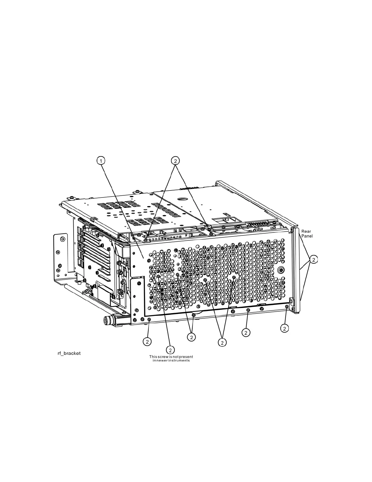
4. Refer to Figure 15-9. Remove the chassis side, right (1) by removing the
thirteen screws (2) using the T-10 driver.
Figure 15-9 RF Bracket Removal

 Loading...


