350 Keysight N9010A EXA Service Guide
Power Supply/Midplane Troubleshooting
A6 Power Supply Basic Troubleshooting (Cover On)
A6 Power Supply Basic Troubleshooting
(Cover On)
1. Ensure the instrument is plugged into a known good AC power source and
the yellow standby LED near the power on switch is illuminated. A lit
yellow LED indicates the +5.1 SB VDC power supply voltage is providing
enough voltage to light the LED.
2. Power on the instrument and verify that the green LED on the front panel
is lit. A lit LED indicates the power supply has received an “ON” command
from the A4, CPU assembly and that the +5.2A VDC supply is on.
3. Verify both fans are operating on the side panel of the instrument. The fans
can be heard once the analyzer is powered up. If the fans are operating,
the fan power supply is functioning.
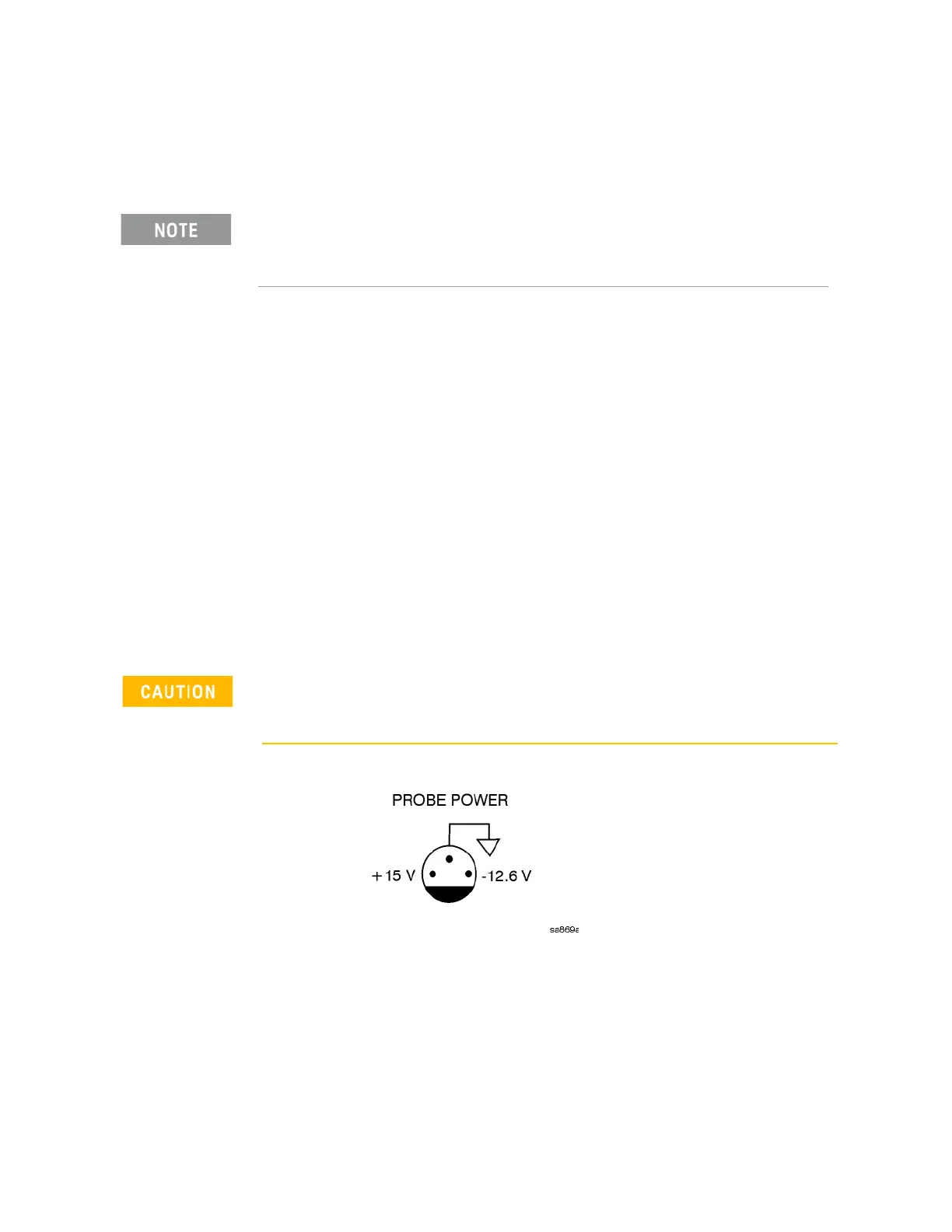
4. The front panel probe power connector can be used to check the +15 VDC
(+/- 7%) and -12.5 VDC (+/-10%) supplies. The -12.5 VDC is produced by
post regulating the -15 VDC supply. A voltmeter can be used to verify
these supplies. Refer to Figure 10-2 for a diagram of the probe power
connector.
Figure 10-2 Probe Power Connector
If these initial checks are functioning properly and yet the signal analyzer will
not boot up properly, or the display is not turning on, refer to Chapter 2, “Boot
Up and Initialization Troubleshooting” in this service manual.
There are no user replaceable fuses on the power supply. If the internal fuse is blown, the power
supply has experienced a major failure and should be replaced. If you determine that the power
supply is the failed assembly, replace the power supply. If the power supply is suspect, perform
the following quick checks before removing the instrument cover.
Exercise great care when measuring voltages on the Probe Power connector. Accidentally
shorting the +15V or -12.6V supply to ground can cause damage to the A1A2 or A1A5
assemblies.

 Loading...


