Keysight N9010A EXA Service Guide 495
Assembly Replacement Procedures
RF Area (Option 503, 507, 513, 526)
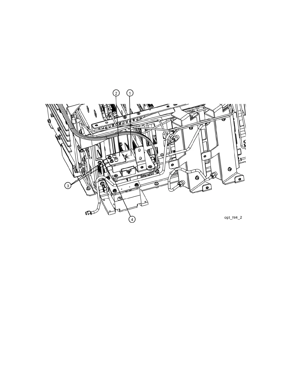
6. Refer to Figure 15-25. Place one of the two coaxial switches (1) and the
Switch 1 Bracket (2) onto the low band switch bracket. Mount the switch
with the Keysight label facing up. Attach the bracket and switch to the low
band switch bracket using two 0515-1992 screws (3) using the T-8 driver.
Do not torque the screws at this time
Figure 15-25 Switch 1 Placement

 Loading...


