494 Keysight N9010A EXA Service Guide
Assembly Replacement Procedures
RF Area (Option 503, 507, 513, 526)
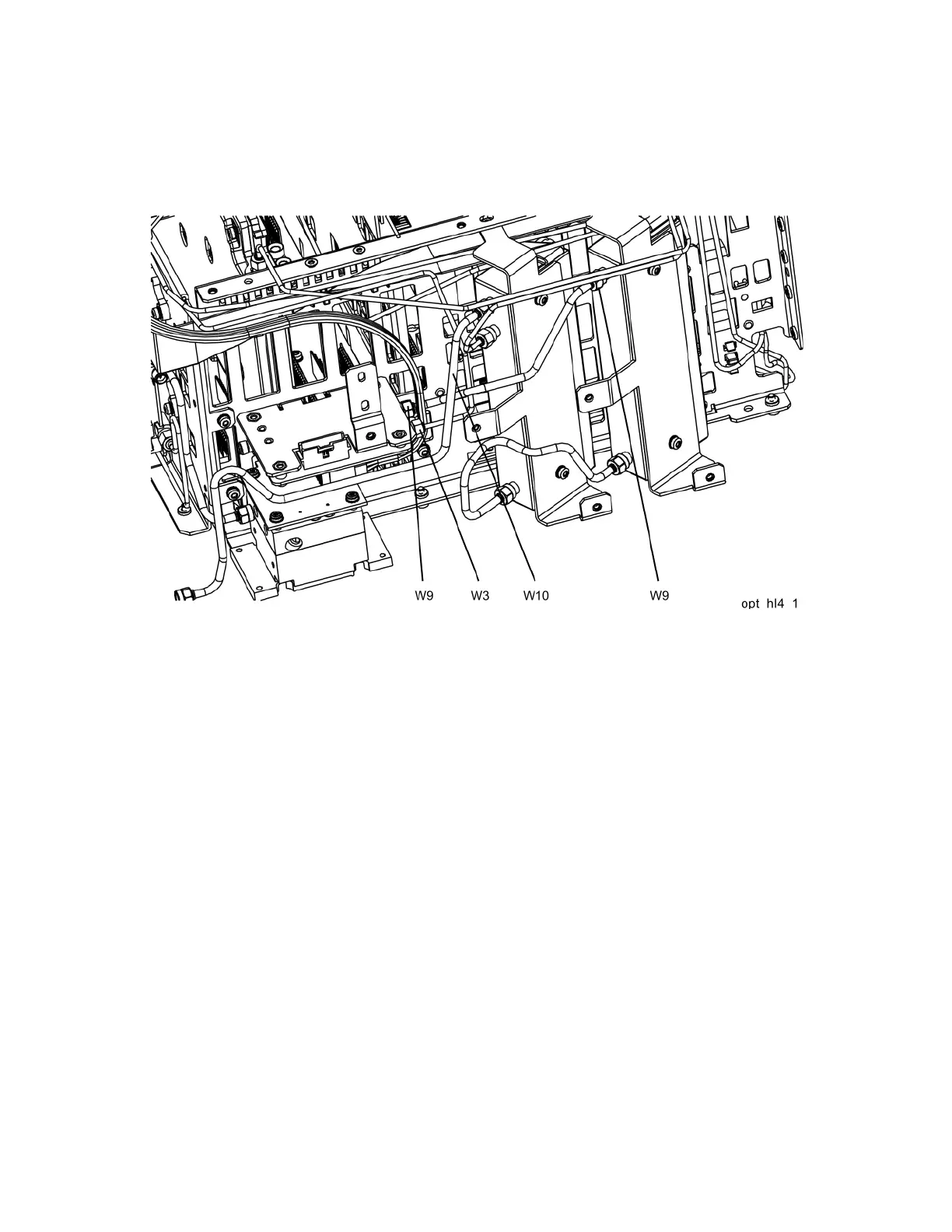
3. Refer to Figure 15-24. Install W9 between the output of the A10 Input
Attenuator and A11J1. Torque to 10 inch-pounds.
Figure 15-24 Installing New Coax Cables
4. Install W3 between J2 of the A13 Front End Assembly and J2 of the A11
Low Band Switch. Torque to 10 inch-pounds.
5. Install W10 between the Type N input connector and the input of the A9
Input Attenuator. Torque to 10 inch-pounds.

 Loading...


