Keysight N9010A EXA Service Guide 493
Assembly Replacement Procedures
RF Area (Option 503, 507, 513, 526)
Replacement
1. Refer to Figure 15-22. Place the switch onto the low band switch bracket
and replace the four screws (3). Torque to 9 inch-pounds in the sequence
shown, starting with #1.
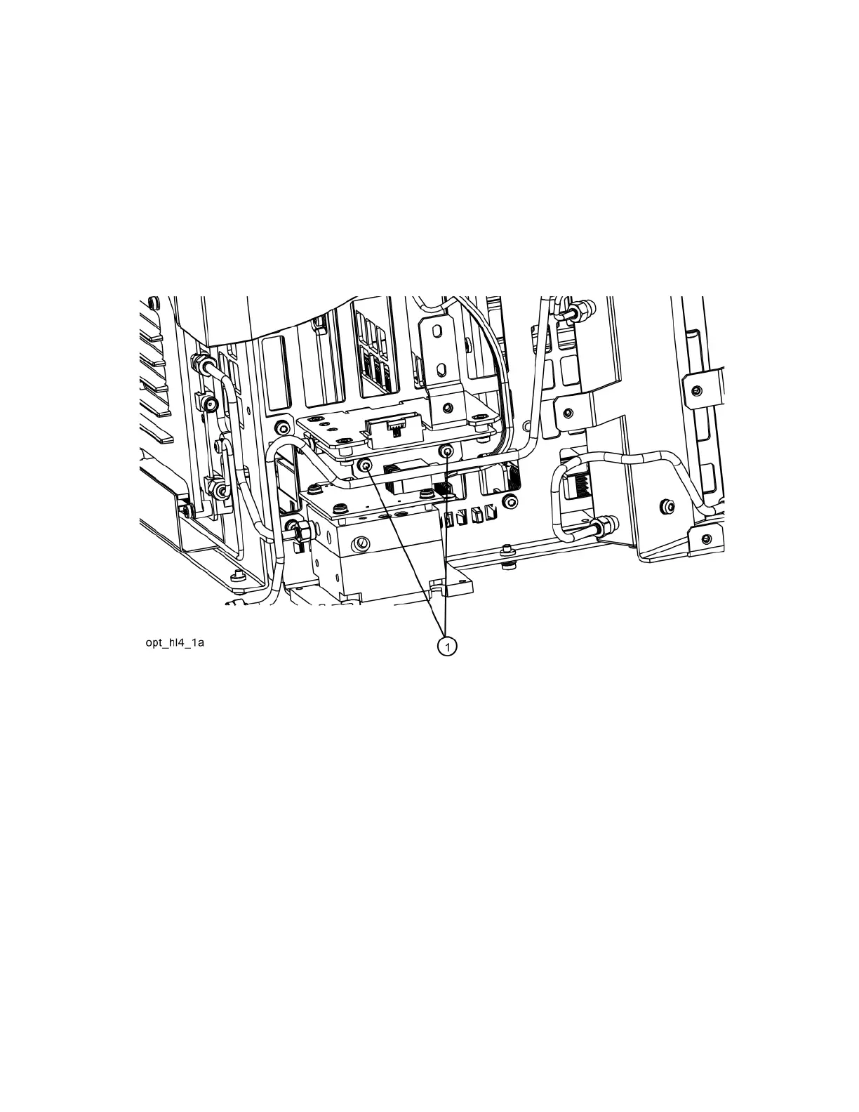
2. Refer to Figure 15-23. Place the switch/bracket into place onto the
chassis and replace the two screws. Torque to 9 inch-pounds starting with
the screw closest to the front of the instrument.
Figure 15-23 Bracket Installation

 Loading...


