L-Gate User Manual 22 LOYTEC
Version 3.2 LOYTEC electronics GmbH
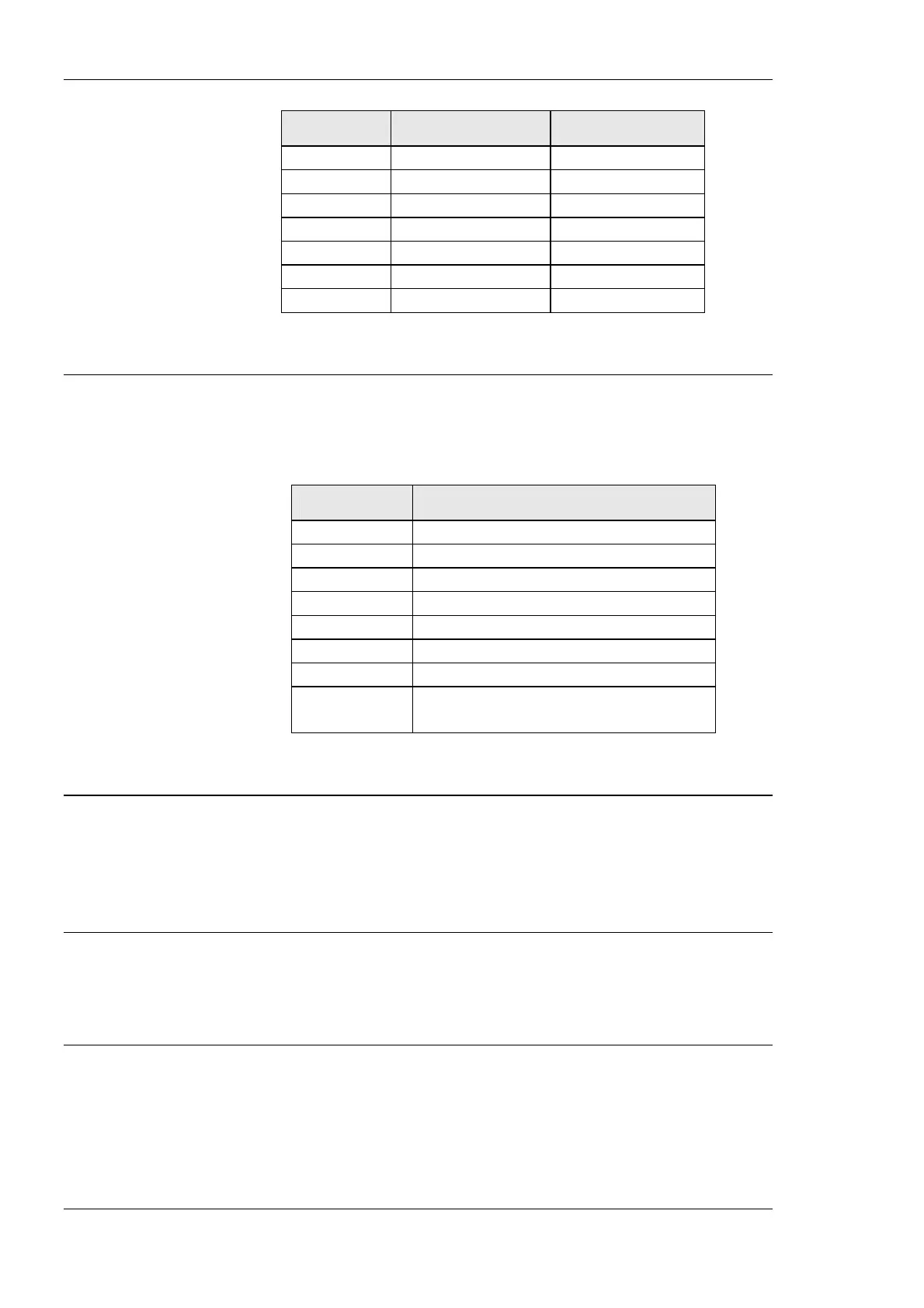
DIP Switch # Function Factory Default
1 Must be OFF OFF
2 Must be OFF OFF
3 Must be ON ON
4 Must be OFF OFF
5 Must be OFF OFF
6 Must be OFF OFF
7 Must be OFF OFF
Table 3: DIP Switch Settings for L-Gate
3.7 Terminal Layout and Power Supply
The L-Gate provides screw terminals to connect to the network as well as to the power
supply. The screw terminals can be used for wires of a maximum thickness of 1.5
mm
2
/AWG12. The device can either be DC or AC powered.
Terminal Function
1 BACnet MS/TP Ground
2 BACnet MS/TP Non-Inverting Input
3 BACnet MS/TP Inverting Input
4 Earth Ground
5, 6 CEA-709 A, B of FT-10 Channel Port
8 Ethernet 100BaseT
15 Earth Ground
16, 17 Power Supply 12-35 VDC or 12-24 VAC ± 10%
Do not connect terminal 17 to earth ground!
Table 4: L-Gate Terminals LGATE-900.
3.8 Wiring
The CEA-709 network segment connected to the L-Gate needs to be terminated according
to the rules found in the specification of the transceiver (see Section 8.1). If BACnet is
configured to run over MS/TP, the MS/TP network segment must be properly terminated
with an LT-04 network terminator connected at each of the two ends of the segment media.
Important: When using shielded network cables, only one side of the cable should be connected to
earth ground. Thus, the shield must be connected to earth ground either at the L-Gate
terminals or somewhere else in the network.
Important: When using 2-wire MS/TP, earth ground must be connected to both terminal 15 and 16
(see Figure 9a). Never connect terminal 17 to earth ground!