Maximu
m
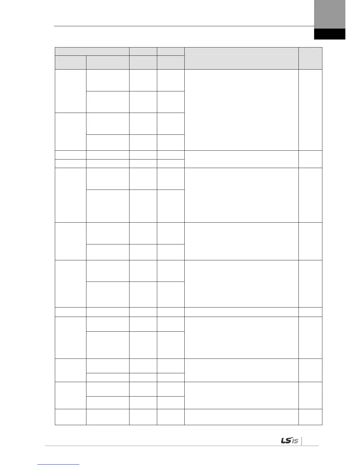
P0-19
DAC output
offset 1
(MONIT1)
[Unit/V] 0
Sets offset for 1-2 analog output channels.
Speed: [RPM]
Torque: [%]
Position command frequency: [0.1 Kpps]
Position: [pulse]
DC Link: [V]
Offset
(Details: Refer to “4.4.1 System Parameter
Setting.")
PST
DAC output
offset 1
(MONIT1)
-1000 1000
P0-20
DAC output
offset 2
(MONIT2)
[Unit/V] 0
DAC offset 2 (F)
(MONIT2)
-1000 1000
P0-21 Reserved
P0-22 Reserved
P0-23
DAC output
scale 1
(MONIT1)
[Unit/V] 500
Sets magnification for 1-2 analog output
channels.
Sets magnification as setting Unit/V.
E.g.) Channel 1 scale 100 [RPM]: Output 100
[RPM] as 1 [V].
(Details: Refer to “4.4.1 System Parameter
Setting.")
PST
DAC scale1 (F)
(MONIT1)
1 10000
P0-24
DAC output
scale 2
(MONIT2)
[Unit/V] 500
PST
DAC scale 2 (F)
(MONIT2)
1 10000
P0-24
DAC output
scale 2
(MONIT2)
[Unit/V] 500
Sets magnification for 1-2 analog output
channels.
Sets magnification as setting Unit/V.
E.g.) Channel 1 scale 100 [RPM]: Output 100
[RPM] as 1 [V].
(Details: Refer to “4.4.1 System Parameter
Setting.")
PST
DAC scale 2 (F)
(MONIT2)
1 10000
P0-25 Reserved
P0-26
Encoder function
setting
- 0
Multi turn encoder function setting
*0: Using as Multi turn mode with multi turn
encoder.
*1: Using as Single turn mode with multi turn
encoder.
(Applied from OS Ver 1.29)
PST
0 1
P0-27
U phase Current
Offset value
[mA] 0
Store U phase Current Offset value.
PST
U Current Offset -9999 9999
P0-28
V phase Current
Offset value
[mA] 0
Store V phase Current Offset value.
PST
V Current Offset -9999 9999
P0-29 Reserved

 Loading...
