1. Product Components and Signals
2-7
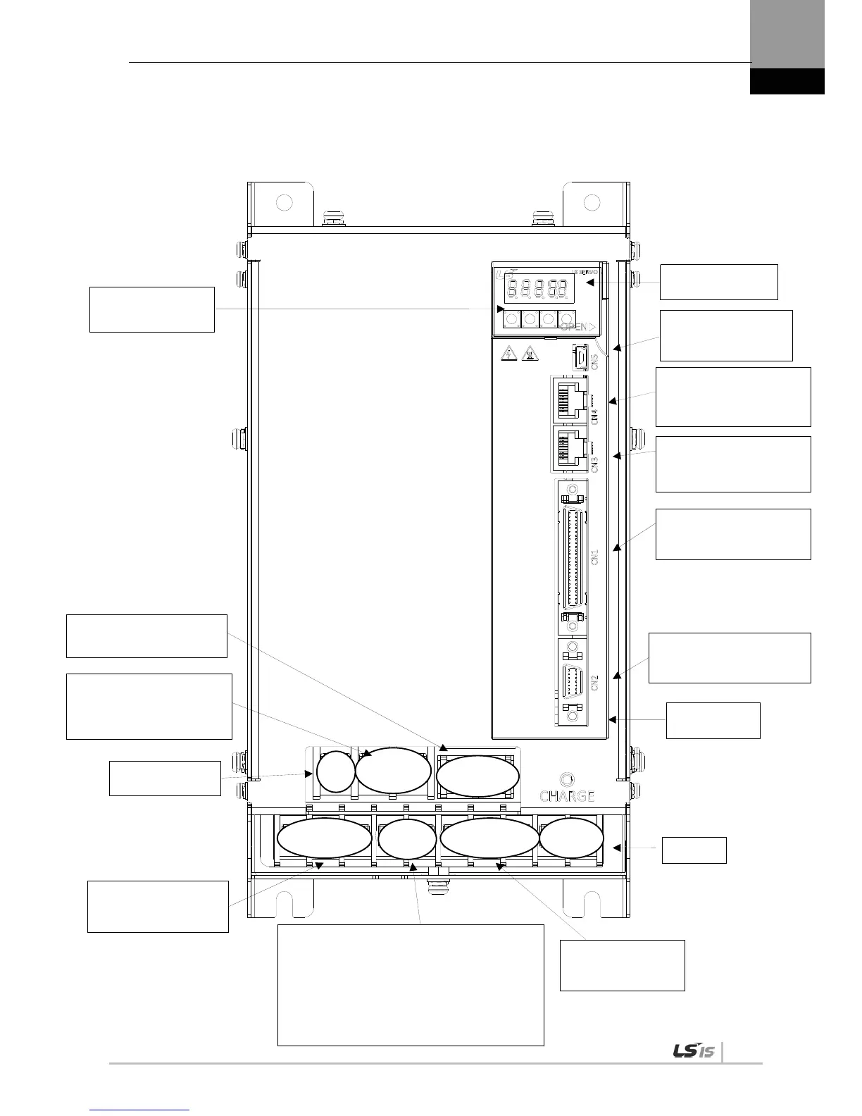
XDL-L7SA 050
Main power connector
(L1, L2, L3)
Regenerative resistance connector (B+, B)
When basic installation is in use,
leave it.
When installing external resistance,
install in the B+ and B terminals after
attaching wires of internal resistance to
“NC” hole on the case.
Motor power cable
connector (U, V, W)
Display
CN5:
USB Connector
CN4:
RS-422 Communication
connector
CN3:
RS-422 Communication
connecto

 Loading...
