4. Parameters
4-18
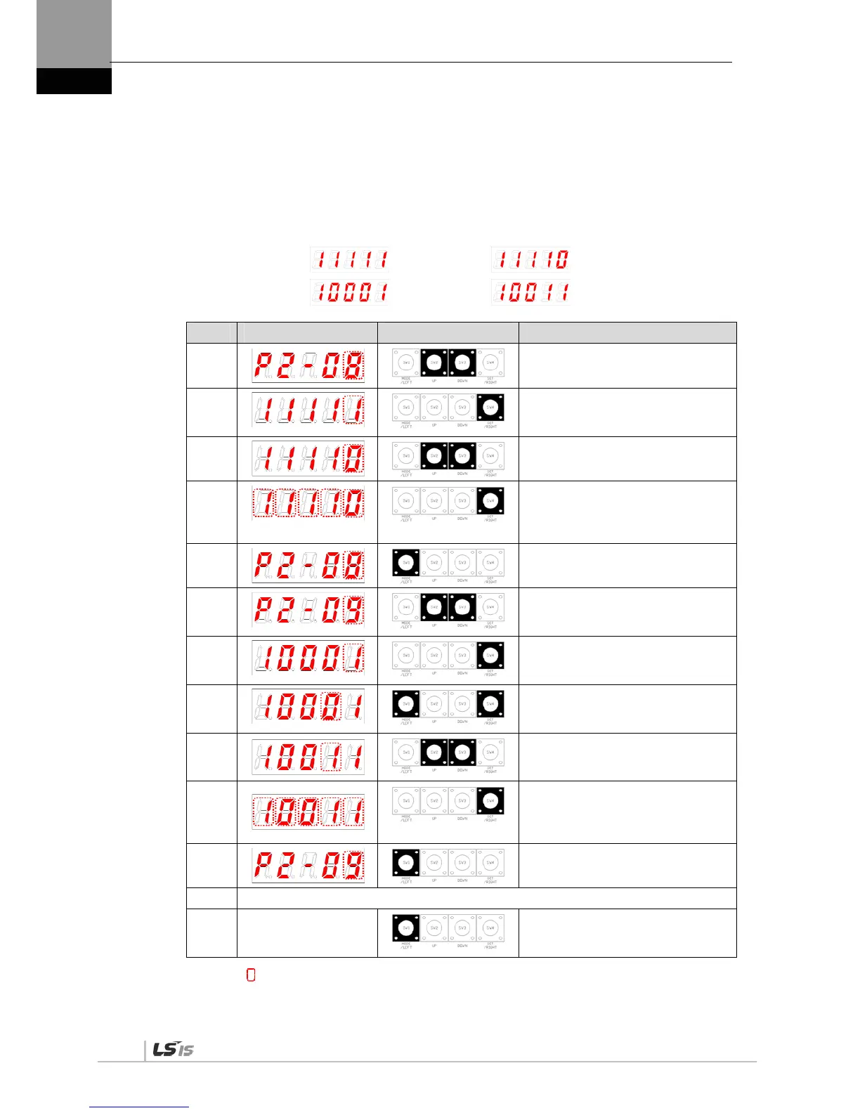
Examples of changing input signal logic definitions
The table below shows examples of changing input signal logic definitions.
The sequence of changing logic signal contact A of SVON (CN1-47) to contact B and logic
signal contact B of CCWLIM (1-20) to contact A is as follows.
Before changing After changing
[P2-08]:
[P2-09]:
Order Loader Displays Keys to Use What to Do
1
Press [UP] or [DOWN] at the blinking
cursor to move to [P2-08].
2
Press [SET] to enter parameter edit
mode. The parameter is displayed as
11111.
3
Press [UP] or [DOWN] at the blinking
cursor to change the number to 11110.
4
Hold down [SET] for approximately
one second. After two flickers, the
number is saved as 11110 for the
parameter.
5
Hold down [MODE] for approximately
one second to return to [P2-08].
6
Press [UP] or [DOWN] at the blinking
cursor to change the number to [P2-
09].
7
Press [SET] to enter parameter edit
mode. The parameter is displayed as
10001.
8
Press [/LEFT] or [/RIGHT] at the
blinking cursor to move to the desired
digit, DIGIT 2.
9
Press [UP] or [DOWN] at the blinking
cursor to change the number to
10011.
10
Hold down [SET] for approximately
one second. After two flickers, the
number is saved as 10011 for the
parameter.
11
Hold down [MODE] for approximately
one second to return to [P2-09].
12 ** Modification is not possible with the servo on &. Reset the parameter.
※
In case of exiting
without saving the set
value
Hold down [MODE] for approximately
one second to return to the parameter.
NOTE 1) “ ” indicates flickering.

 Loading...
