4. Parameters
4-17
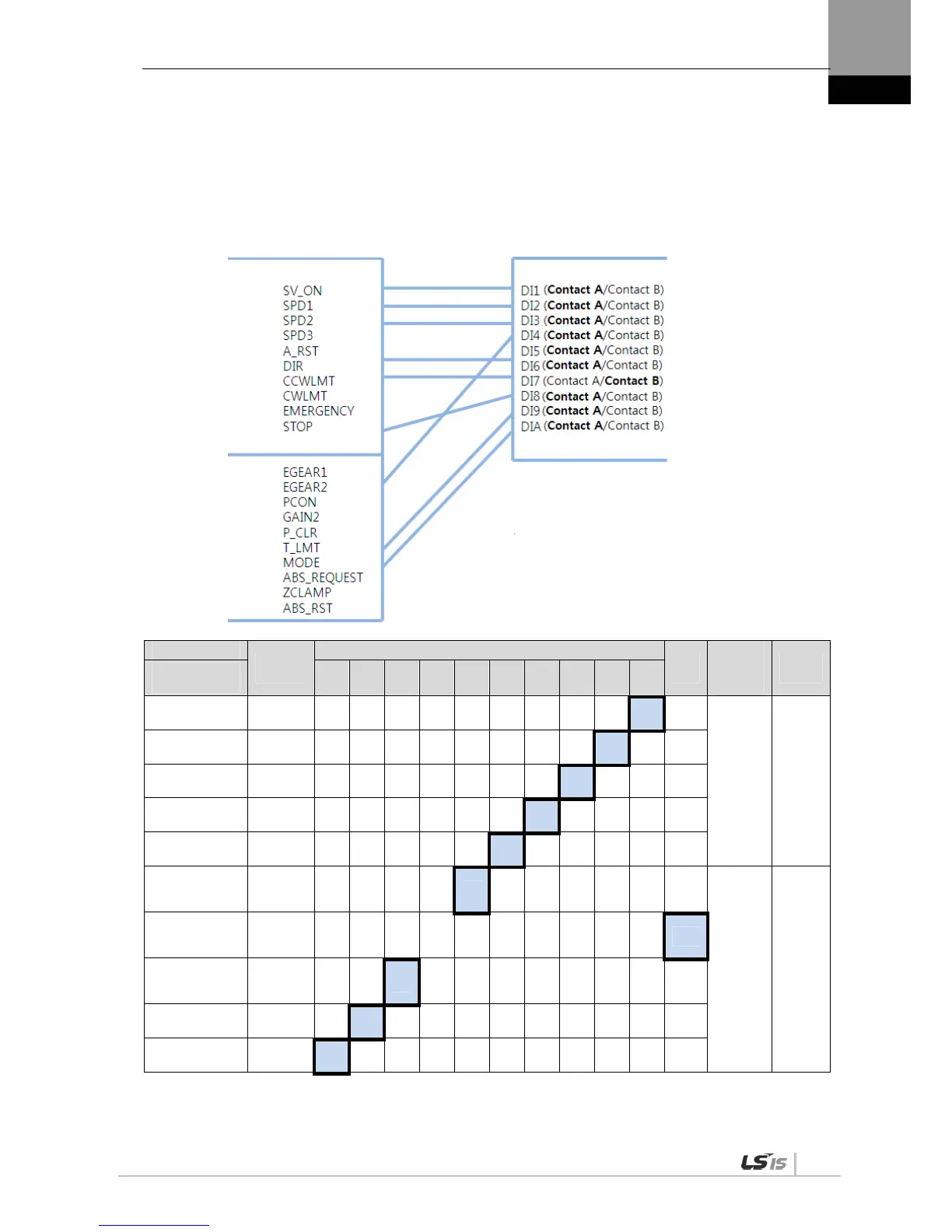
(4) Example of Changing Input Signal Logic Definitions
Input signal logic definitions can be changed in [P2-08] and [P2-09].
When input signals are allocated as below, settings will be done as shown in table below.
Signal Name
Input
Signal
CN1 Pin Default Allocation Number
Cont
act B
Input
signal
logic
definition
Default
setting
Parameter
Allocation
48 18 19 20 46 17 21 22 23 47
Servo ON
[P2-08].Set Digit 1
SVON
1 0
[P2-08] 0x11111
Multi-speed 1
[P2-08]. Set Digit 2
SPD1
1 0
Multi-speed 2
[P2-08]. Set Digit 3
SPD2
1 0
Multi-speed 3
[P2-08]. Set Digit 4
SPD3
1 0
Alarm reset
[P2-08]. Set Digit 5
ALMRST
1 0
Select rotation
direction
[P2-09]. Set Digit 1
DIR 1 0
[P2-09] 0x11101
Forward rotation
prohibited
[P2-09]. Set Digit 2
CCWLIM 0
Reverse rotation
prohibited
[P2-09]. Set Digit 3
CWLIM 1 0
Emergency stop
[P2-09]. Set Digit 4
EMG
1 0
Stop
[P2-09]. Set Digit 5
STOP
1 0
NOTE 1) For the purpose of the input signal logic definition, Contact A is 1 and Contact B is 0.
Input signal logic definition
Input signal logic definition number

 Loading...
