4. Parameters
4-24
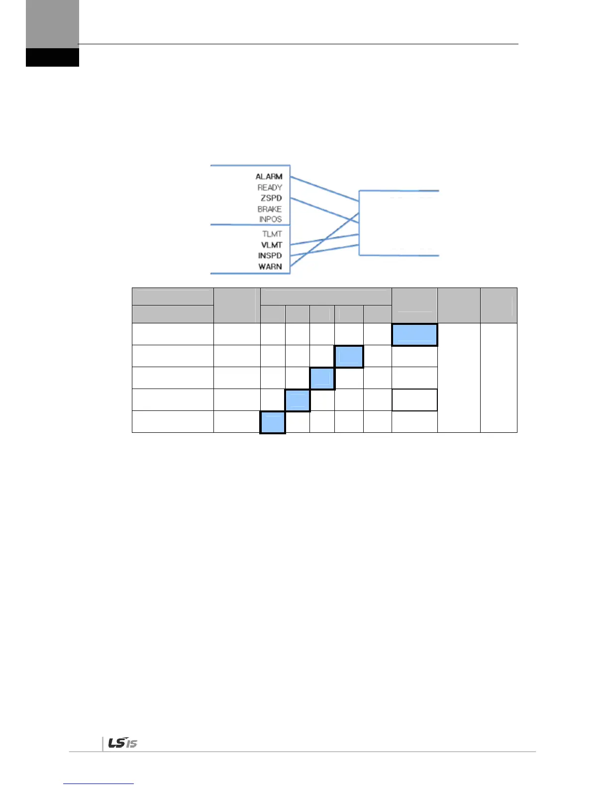
(4) Examples of Changing Output Signal Logic Definition
Output signal logic definitions can be changed at [P2-10]
Set output signals as shown in the table below when they are allocated as below.
Signal Name
Input
Signal
(Initial
Name)
CN1 Pin Default Allocation Number
Contact B
Output
Signal
Logic
Definition
Default
Setting
Parameter Allocation 45 44 43 40 /41 38 /39
Alarm
[P2-10].Set Digit 1
ALARM
0
[P2-10] 0x11110
Servo Ready
[P2-10]. Set Digit 2
READY
1 0
Zero speed achieved
[P2-10].Digit 3
ZSPD
1 0
Brake
[P2-10].Digit 4
BRAKE
1 0
Position reached
[P2-10].Digit 5
INPOS
1 0
For the purpose of the input signal logic definition, Contact A is 1 and Contact B is 0
Output signal logic definitions
Output signal logic definition number
DO1(Contact A/Contact B)
DO2(Contact A/Contact B)
DO3(Contact A/Contact B)
DO4(Contact A/Contact B)
DO5(Contact A/Contact B)

 Loading...
