4. Parameters
4-25
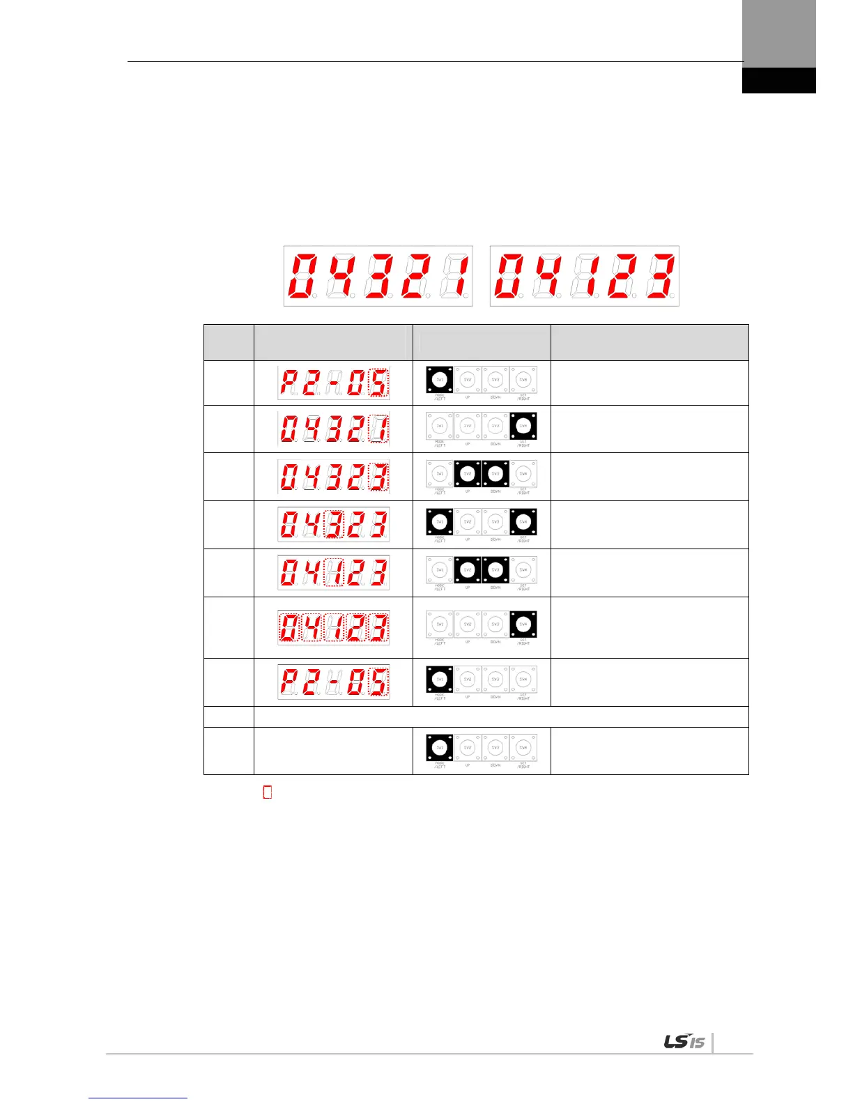
Example of Changing Output Signal Allocation
The following is an example of output signal allocation change.
The sequence of switching the allocation signals of ALM (CN1-38/39) and ZSPD (CN1-43) is
as follows:
Before Changing After Changing
[P2-05]:
Order
Loader Window
Display Result
Keys to Use What to Do
1
Press [MODE] to move to [P2-05].
2
Press [SET] to enter parameter
edit mode. The parameter is
displayed as 04321.
3
Press [UP] or [DOWN] at the
blinking cursor to change the
number to 04323.
4
Press [/LEFT] or [/RIGHT] at the
blinking cursor to move to the
desired digit, DIGIT 3.
5
Press [UP] or [DOWN] at the
blinking cursor to change the
number to 04123.
6
Hold down [SET] for approximately
one second. After two flickers, the
number will be saved as 04123 for
the parameter.
7
Hold down [MODE] for
approximately one second to
return to [P2-05].
8 ** Modification is not possible with the servo on & Reset the parameter.
※
In case of exiting without
saving the set value
Hold down [MODE] for
approximately one second to
return to the parameter.
NOTE 1) “ “indicates flickering.
If two output signals are allocated to a number, the output contact setting error [AL-72] alarm
will be triggered.

 Loading...
