4-4 (E)
LH71A / LH72
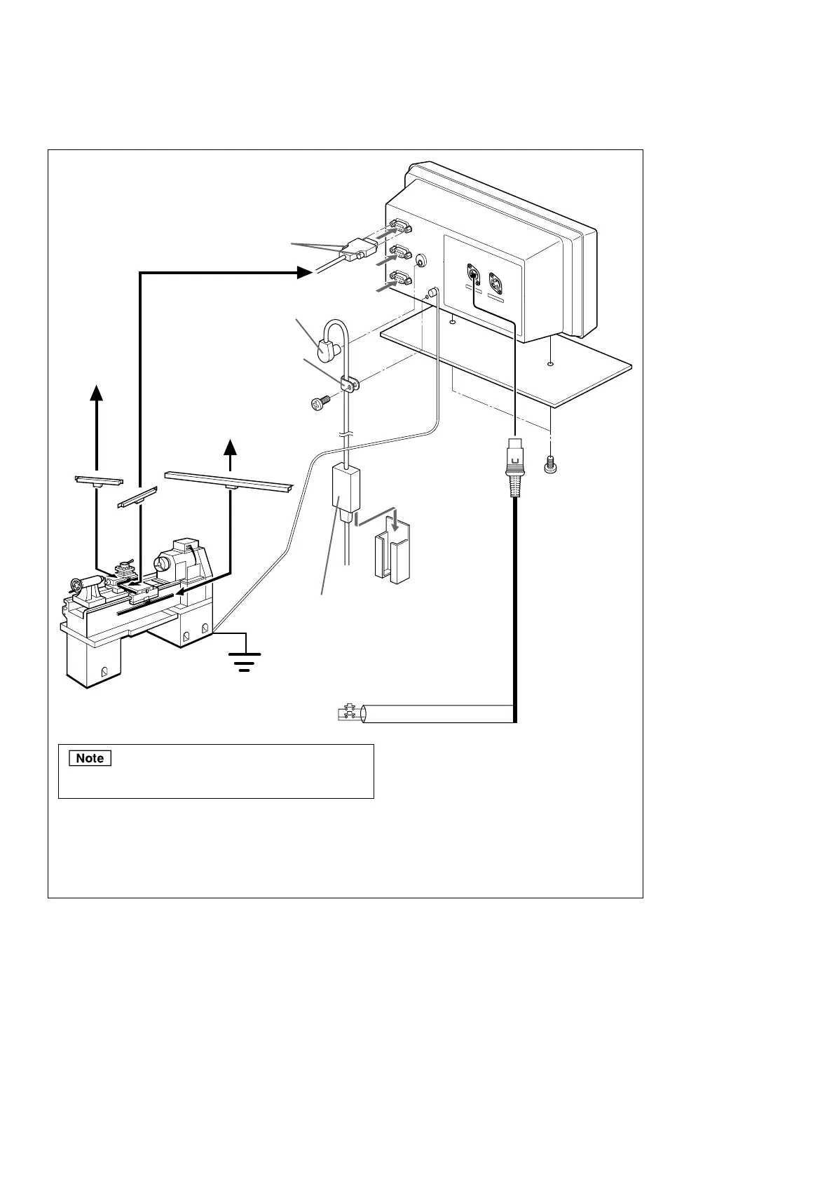
Connections when using the addition function with lathe function
*1
To the second
or third axes
Screw down firmly.
Clamp the cable to prevent the
connector from pulling out.
Provide slack as shown to
ensure that force is not being
applied to the connector.
Bracket
M4 × 16 anchor
bolts, 2 pcs.
(supplied)
PSC-21/22/23 AC adaptor (sold separately)
100 - 240 VAC±10% 50/60 Hz
∗ Get power from lamp line.
Measuring unit input
First axis
2
3
DC output connector
*1
To the
second or
third axes
To the first axis
∗1 If the resolutions of the measuring units performing the addition (Z
1
-axis, Z
2
-axis) are different, be sure
to connect the measuring unit with higher resolution to the second axis of the counter unit.
Example: Using measuring unit Z1 (resolution: 0.5 µm) and measuring unit Z2 (resolution: 1 µm)
Measuring unit Z
1
(resolution: 0.5 µm) : Connected to counter unit second axis
Measuring unit Z
2
(resolution: 1 µm) : Connected to counter unit third axis
Z
2
-axis
Measuring unit
X-axis
Z
1
-axis
Ground
wire
4. Installation and Connection of Unit
Connect the supplied ground wire to ensure that the counter
unit is the same potential as the machine proper.
X-axis
Shielded cable
Remote reset switch
Z-axis
R
E
M
O
TE
RE
S
E
T
T
OU
C
H SE
NSO
R