CHECKS
Check for 12 volts at auxiliary disable valve when enabling cylinders.
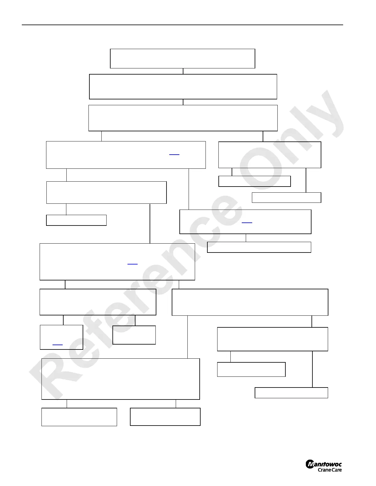
PROBLEM 26
Boom hinge pin or crawler pin cylinders will not operate.
POSSIBLE CAUSES
Faulty relief valve, auxiliary disable valve, proportional control valve or control
valve section; Cylinder failure; Bad pump; Mechanical problem.
12 Volts
No Volts
Check for 3,500 psi at upper valve assembly while enabling any upper
valve assembly control in retract direction. (See Test
25.)
3,500 psi or more
3,500 psi or less
3,500 psi or more
Check for mechanical problem at pin cylinders.
No Problem
Repair as necessary.
Check diagnostic display screen (bank 3) for
change of 4 when enabling cylinders.
Change
No Change
Check disable valve wiring.
Consult dealer/factory.
Adjust auxiliary system disable valve and check pressure.
(See Tes t
25.)
3,500 psi or less
Replace auxiliary system disable valve.
Enable cylinder extend and retract solenoid valves at adapter frame
valve assembly and check that voltage is present.
Voltage
No Voltage
3,500 psi or more
3,500 psi or less
3,500 psi or more 3,500 psi or less
Check for 3,500 psi at auxiliary system disable valve while
enabling any other adapter frame valve section in retract
direction. (See Te s t
25.)
Test cylinder for
leakage (See
Te s t
26.)
Disconnect and plug hoses to problem cylinder
and check pressure.
Replace valve
section.
Disconnect adapter frame valve assembly from proportional
flow control valve and plug valves. Check pressure at
auxiliary system disable valve while enabling any other
adapter frame valve section component.
3,500 psi or more
3,500 psi or less
Repair or replace proportional
flow control valve.
Repair or replace adapter
frame control valve.
Replace appropriate diode
to wire #89D1.
Check for 12 volts at respective cylinder switch
wire #51 or #52.
Voltage
No Voltage
Replace respective switch.
 Loading...


