256 HD96-24-CC-TP User Manual
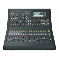
1. The surface uses a 12-segment LED meter in both the banks and surface cong area. These default to monitor pre-fader signal level. Meter range is +20 dB to
-35dB, in 5 dB increments on small meter displays (shown below); 1dB increments on the large meter displays (above).
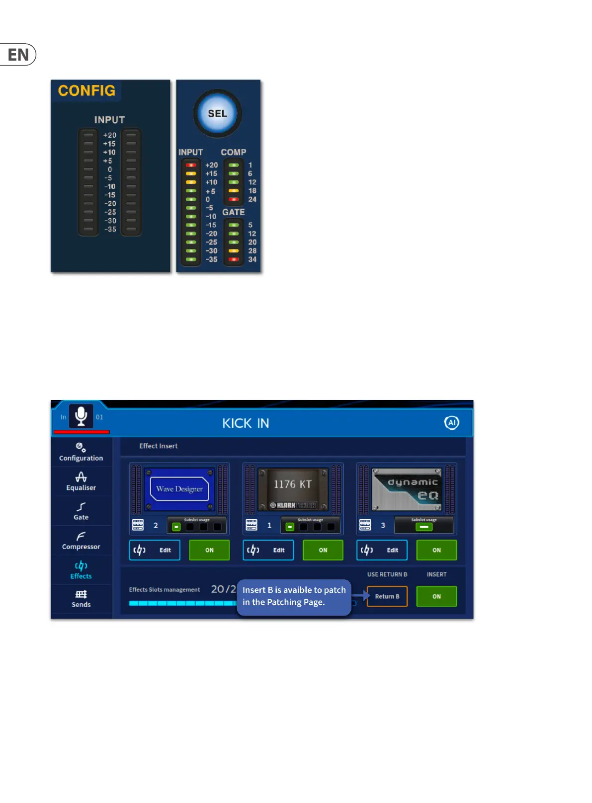
Input Inserts
Input channel insert section provides a send out of - and return to - signal path, primarily so that external dynamic or eects processors can be added to the signal’s
processing. The send destination and return source may only be set from the GUI screen, although the INS button can be found on both the GUI and also in the Cong
area. This section is optional and assigned on a channel-by-channel basis.
A return B path is also available. This takes the place of the Return A path when activated in the channel widgets Eects tab in all workows.
Tip: An example of how to use this could be to run two separate external inserts on a channel with the 2nd external unit as a spare. If the rst external unit fails,
turn on the Return B path.
 Loading...