66 HD96-24-CC-TP User Manual
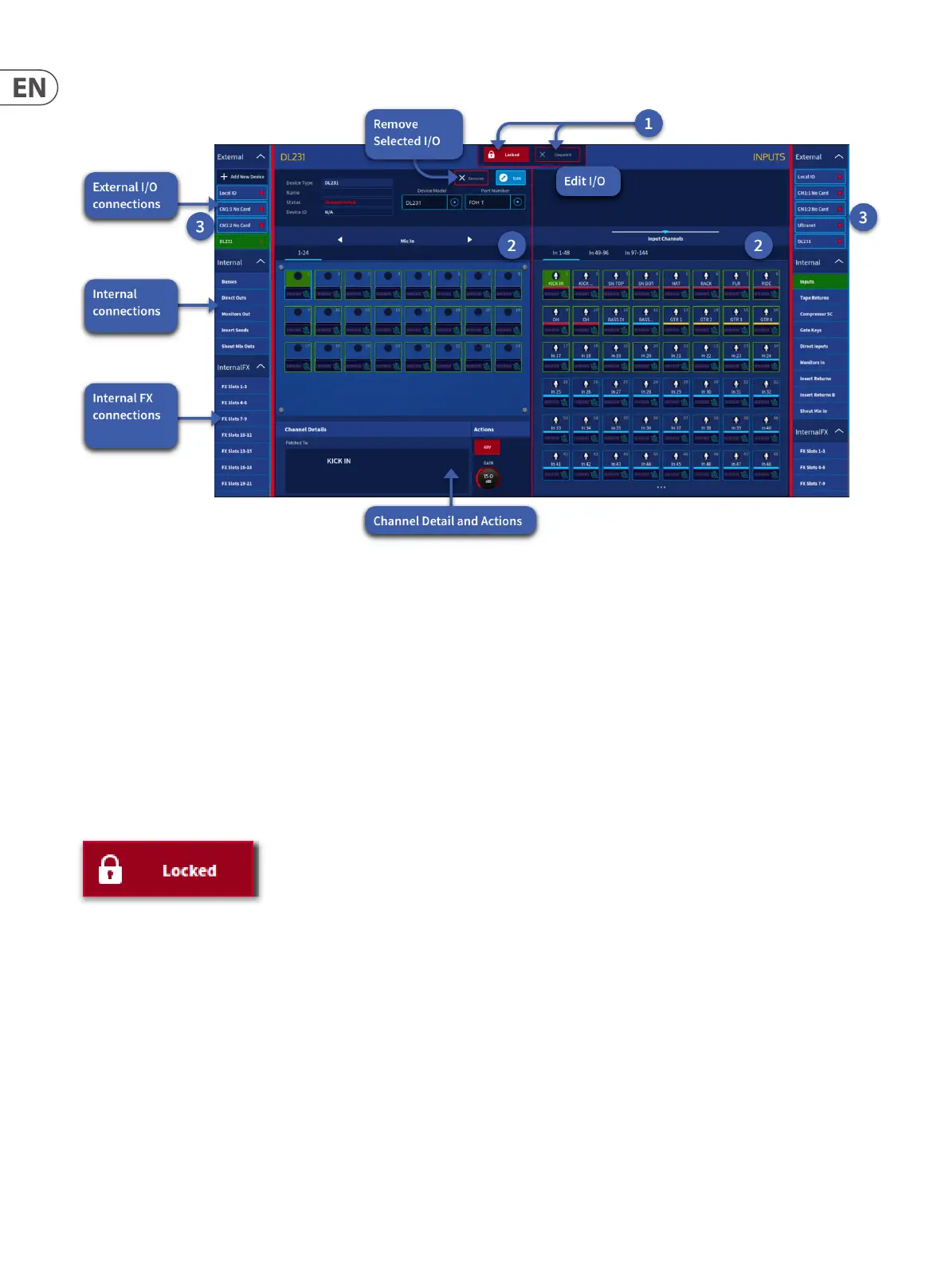
About the Patching screen
The Patching screen can be broken down into three main areas types:
1. The function button panel at the top of the GUI has buttons for Unpatch and Locked. To make any patch changes press the Unlocked button. Note: if you navigate
away from the patching workow the page will automatically lock. Locked mode is a good way to see where patches have been made without accidently
un-patching a channel.
2. The patching areas provides access to all the patch connectors. The two patching areas on both sides can be used in a left to right style to make patches to external
devices or internal functions such as sidechain or tape returns. The patching area is split equally into two independent sections, which contain the source and
destination patch connectors, respectively. The patch connectors are grouped on pages according to type. Only one page per section will be visible at any time and
selected via type or channel number depending on the page and type of device attached.
3. External I/O tab menu. The I/O tabs represent the systems internal patchable items, stage (Remote), 2 x CM-1 slots and FOH/Monitors (Local) racks. Each box
shows the internal and external patchable items devices connected in those racks when selected.
Note: Each time you access the Patching page, the Locked button will be red, and the page will be display-only. This is a safety precaution to prevent any accidental
changes. Before changing any patching, you will need to tap this button, so it turns blue to unlock the patching functionality.
 Loading...