1 - 8
PROCESS
[2] Collimator lens
Figure 16 shows the function of the collimator lens. This lens
is used to form the light which diverges from a point source into
a parallel beam.
[3] Beam combining prism
This prism causes the beams from the two semiconductor
lasers mounted at right angles to each other to be output in the
same direction.
[4] Compression Prism
This prism shapes the beam radiated from each semiconduc-
tor laser, and adjusts the height in the up-down direction.
[5] Fine Adjustment Prism
This prism performs fine adjustment of the beam radiated from
each semiconductor laser in the left-right and up-down direc-
tions.
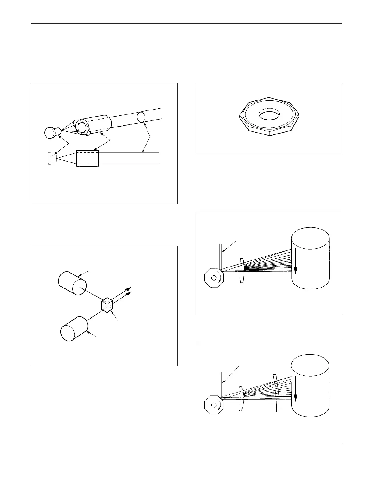
[6] Polygon mirror
This is a multi-sided mirror which converts the laser beam into
a scanning beam. An octagonal mirror is used in this machine.
Figure 18 shows the appearance of the polygon mirror.
Fig.18
[7] f
θ
lens
The polygon mirror rotates at a constant angular speed.
Consequently, if a general image forming lens were to be used,
the speed at which the laser beam scans the surface of the
drum would vary at the center and the both edge of the drum,
as shown in Fig.19.
An f
θ
lens is used to maintain the scanning speed constant
over the entire length of the drum.
Collimator
lens
Semiconductor
laser
Parallel
beam
Fig.16
Semiconductor laser 1
Beam combining prism
Semiconductor laser 2
Fig.17
Fig.20
Polygon
mirror
Cylindrical
lens
Drum;
Scanning
speed is
constant.
Polygon
mirror
Fig.19
Drum;
Scanning
speed falls as
beam
approaches
center of
drum.
Image forming lens
Laser beam
Laser beam
f
θ
lens