2 - I - 7
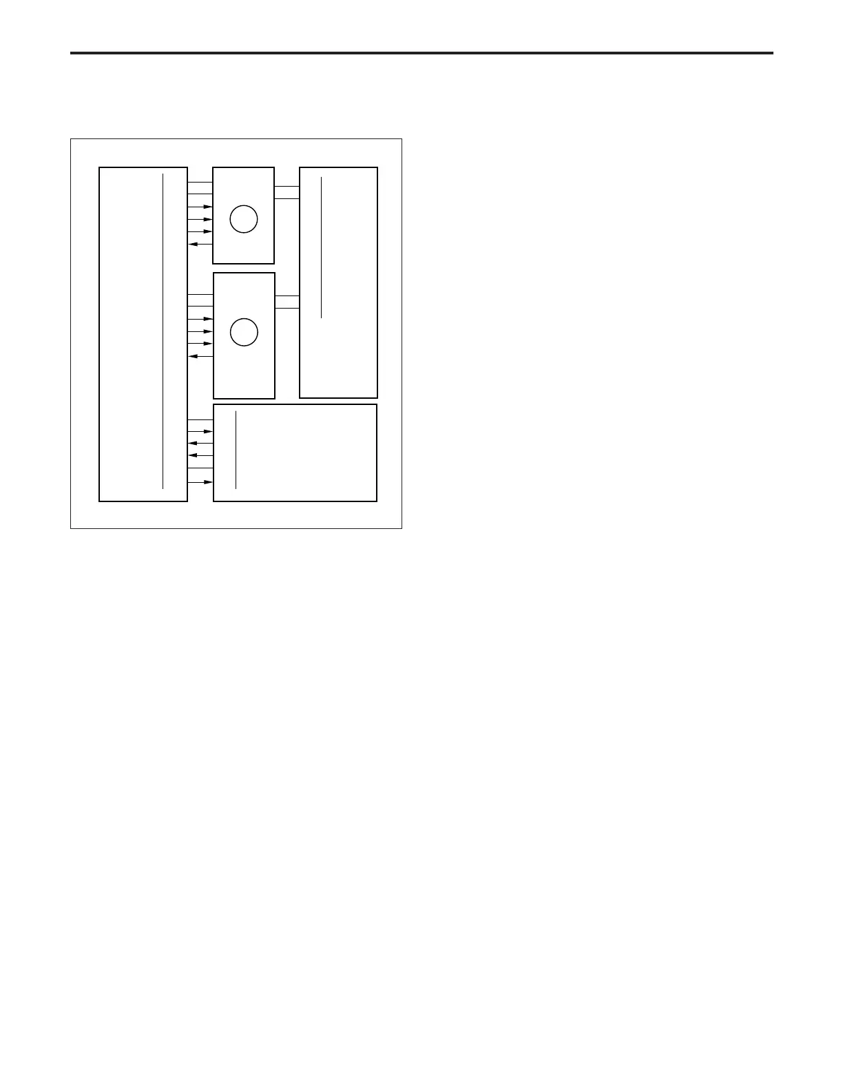
DEVELOPING UNIT
[8] Dmax Control
12VDC
Dmax LED CONT
SGND
γ/Dmax LED V ref
5-B1
5-B2
5-B3
5-B5
5-B6
5-A11
CB
19-2
19-3
19-4
19-6
19-7
19-10
Dmax MONI
Dmax Sig
TCSB
M3
5VDC
SGND
MA CONT
M4 H/L
M4 CLK
M4 PLL
5VDC
SGND
M3 CONT
M3 CLK
M3 H/L
M3 LD
30-A8
30-A9
30-A10
30-B6
30-A11
30-A12
65-B3
65-B4
65-B5
65-B6
65-B7
65-B8
M4
24VDC
PGND
40VDC
PGND
99-2
99-5
88-4
88-2
DCPS
2. Signals
a. Input signals
(1) Dmax sig (TCSB → CB)
Output voltage of the Dmax value detection sensor on
the TCSB
Reference voltage: 1.5 V
(2) Dmax MONI (TCSB → CB)
This is the monitor signal for light reflected from the
drum surface (no toner). The voltage impressed on the
Dmax detection LED is corrected (calibration) by γ/
Dmax LED V ref.
Reference voltage: 6 V
<Implementation timing>
Calibration takes place before Dmax correction.
(3) M3 LD (M3 → CB)
[L] is output when M3 reaches the specified speed.
(4) M4 PLL (M4 → CB)
[L] is output when M4 reaches the specified speed.
b. Output signal
(1) Dmax LED CONT (CB → TCSB)
The control signal used to turn on and off the LED for
PD1 of TCSB.
(2) γ/Dmax LED V ref (CB → TSCB)
DC voltage is supplied to LED of PD1 by this line.
CB changes this voltage until Dmax MONI signal
becomes 6 V.
(3) M3 CLK (CB → M3)
M3 speed control gain switchover signal
(4) M4CONT (CB → M4)
M4 drive control signal
[L]: M4 ON
[H]: M4 OFF
(5) M4 H/L (CB → M4)
M4 rotational speed switchover signal
Normally [H]: 370 mm/sec
(6) M4CLK (CB → M4)
Reference clock signal for controlling the speed of M4
Dmax control is done by the TCSB (toner control sensor
board), M4 (drum), M3 (developing drive), and so on. These
parts are controlled by the CB.
1. Operation
Dmax control is intended to align the maximum density for
each machine with the reference level.
(1) Contents of implementation
Latent images are created several times at the maxi-
mum exposure, the images are developed while the
rotational speed of the sleeve is varied, then each
density is read by the PD1 on the TCSB.
The rotational speed of the sleeve when the density
reaches the reference level is memorized as the opti-
mum sleeve speed, then subsequently developing is
carried out at this sleeve speed until Dmax correction
takes place next.
(2) Implementation timing
1) When the power is switched ON
2) At 500 copies
3) At 1000 copies
2) Every 1000 jobs
2) Every 3000 jobs (see *1)
*1: Can be changed with the 25 Mode software switch.