2 - I - 5
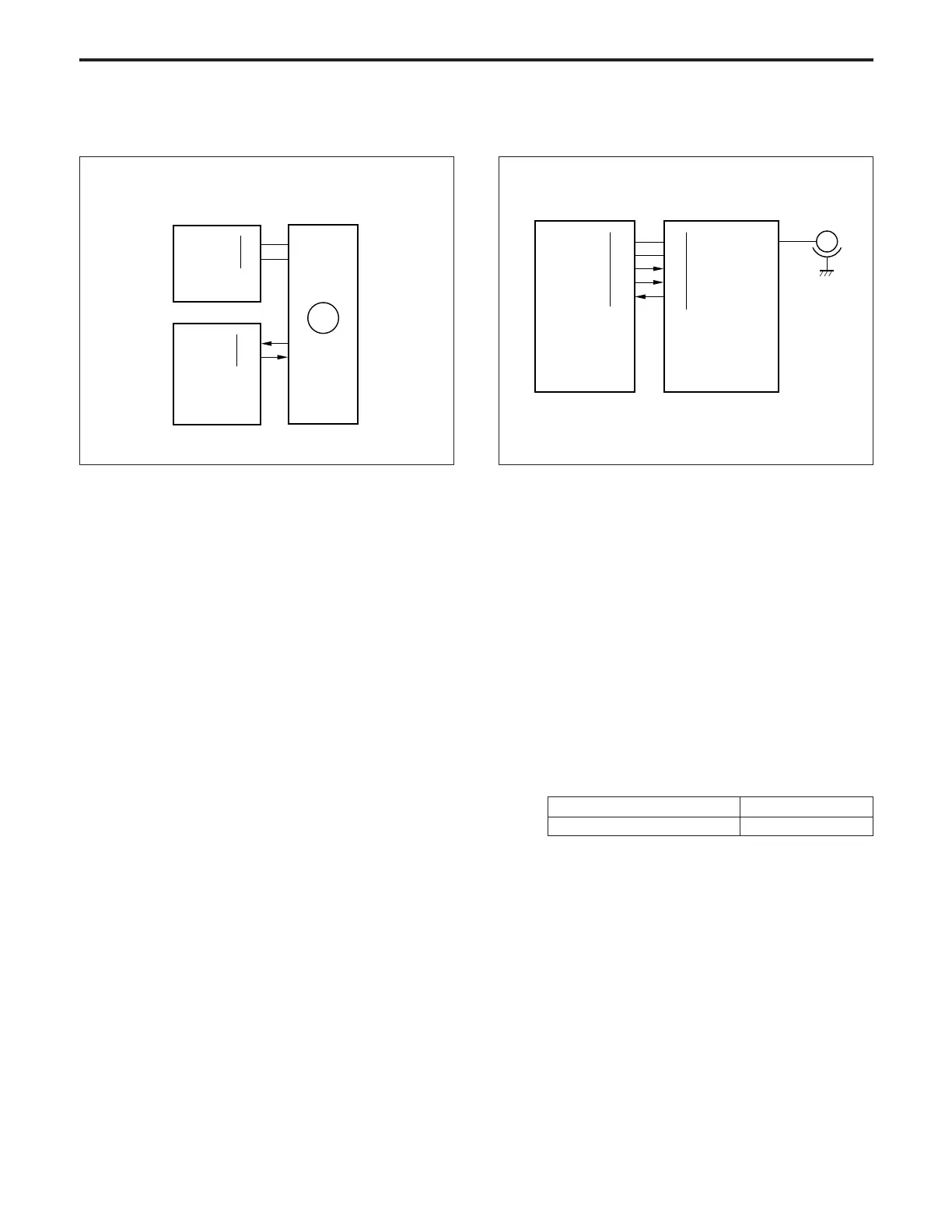
DEVELOPING UNIT
24VDC
PGND
B CONT
B SHIFT
62-A1
62-A2
62-A3
62-A6
62-A9
CB
BIAS
84-1
84-2
84-3
84-6
84-9 F SIG
HV1
B SHIFT output range 2 to 8 V
Bias voltage output range –440 to –700 V DC
24VDC
PGND
99-2
99-5
DCPS
M35 PLL
M35 DRIVE
30-A6
30-A7
CB
M35
[5] M35 (agitator screw) Control
M35 (agitator screw) is controlled by the CB (control board).
1. Operation
M35 is a 24 V DC motor which drives the agitator screw and
the agitator wheel. M35 is PLL-controlled using feedback
signals from the speed sensor installed inside M35, main-
taining it at a constant speed.
M35 goes ON when the Start Print is pressed, and goes
OFF again when the last copy has been exited.
If the upper fixing roller does not reach the set temperature
within the specified time from the start of warmup, M35
goes ON/OFF in synchronism with M1 (main) until comple-
tion of warmup because recycle section is operated by M1.
2. Signals
a. Input signal
(1) M35 PLL (M35 → CB)
[L] is output when M35 reaches the specified speed.
b. Output signal
(1) M35 CONT (CB → M35)
M35 drive control signal
[L]: M35 ON
[H]: M35 OFF
[6] Developing Bias Control
The developing bias is controlled by the CB (control board) via
HV1 (high voltage power supply 1).
1. Operation
The developing bias is applied to the sleeve in synchronism
with M3 (developing drive).
2. Signals
a. Output signals
(1) B CONT (CB → HV1)
Developing bias ON/OFF control signal.
When this signal is [L], the developing bias goes ON,
and a high voltage is output.
(2) B SHIFT (CB → HV1)
This signal controls the output level of the developing
bias by means of analog signals from the CB.