2 - S - 13
FIXING UNIT
(b) When adjusting the distance, should not be al-
lowed to run up over B .
B
A
(2) Coat the set screw of the installed thermostat (lower)
with screw lock agent.
(3) Connect the two fastons.
(4) Re-install the other parts in the opposite sequence to
removal.
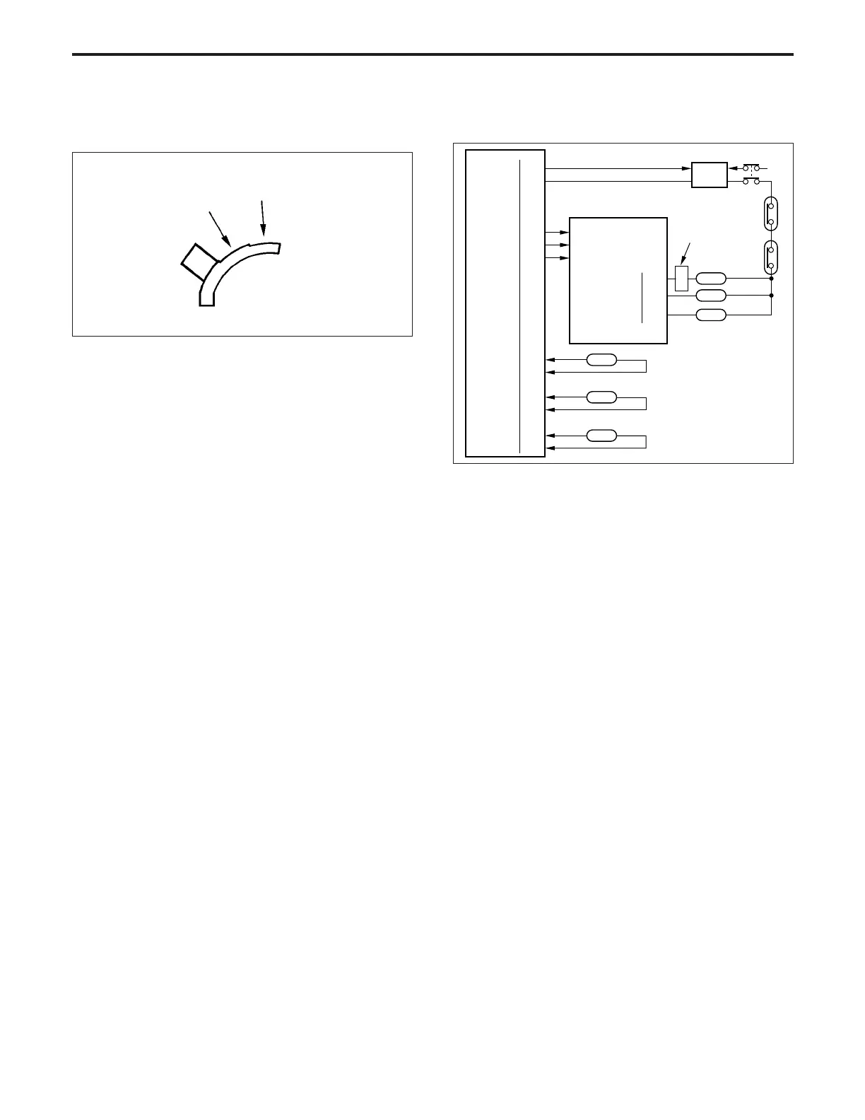
[4] Fixing Temperature Control
The upper fixing roller is heated by L2 (fixing heater lamp 1),
and L3 (fixing heater lamp 2), and the lower fixing roller is
heated by L4 (fixing heater lamp 3). The CB detects the
temperature of the fixing rollers by means of TH1 (fixing
temperature sensor 1) and TH3 (fixing temperature sensor 3),
and controls L2, L3 and L4 via DCPS.
1. Operation
a. Temperature control
(1) Warmup
The CB (control board) turns ON the fixing heater lamp
circuit in DCPS (DC power supply unit ) as soon as the
main switch is turned ON, causing L2 , L3, L4 and M1
(main) to go ON until the upper fixing roller reaches the
specified temperature. After finish warmup, L3 and L4
goes ON and OFF in synchronism with L2. If the upper
fixing roller does not reach the specified temperature
within a certain time from the start of warmup, L2 and
L4 remain ON and also M1 (main) goes ON until the
completion of warmup.
(Set Temperature)
200°C/392°F
(Warm up time)
Approx. 7min. (Room temp : 20°C/68°F)
RL DRIVE
24VDC
L2 CONT
L3 CONT
L4 CONT
TH1 ANG 1
TH1 ANG 2
TH2 ANG 1
TH2 ANG 2
TH3 ANG
SGND
8-3
8-2
8-1
L2 DRIVE
L3 DRIVE
L4 DRIVE
382-2
382-4
DCPS
CB
RL1
AC
TS1
TS2
L3
L2
L4
TH1
60-B9
60-B10
60-A6
60-A7
60-A8
6-B1
6-B2
6-B3
6-B4
6-A12
6-B5
TH2
TH3
MS4
CN 399-1