2 - H - 6
CORONA UNIT SECTION
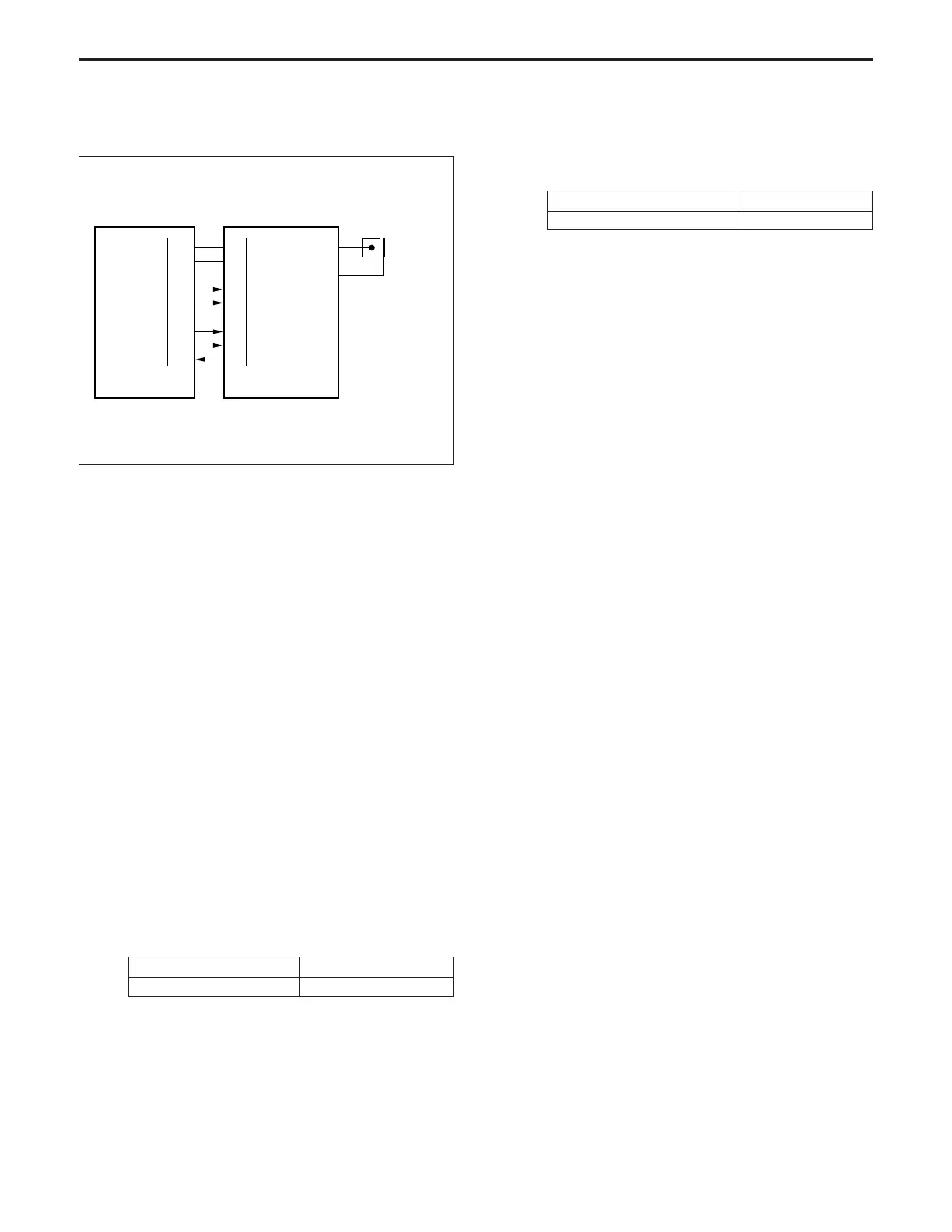
[4] Charging Control
HV1 (high voltage unit 1), which controls charging, operates by
means of control signals from the CB (control board), and
outputs a high voltage to the charging wires.
1. Operation
a. Charging
A Scorotron charging method is used. 24 V DC input from
the CB is raised to a negative DC high voltage which is then
discharged.
b. Charging correction by means of the grid voltage
The grid voltage is output from HV1 to the charging plate.
2. Signal
a. Input signal
(1) F SIG (HV1 → CB)
[L] is output when the spark detection circuit operates
and forcibly turns OFF the charging output.
b. Output signals
(1) C CONT (CB → HV1)
Charging and grid voltage ON/OFF control signal
[L]: Charging and grid voltage ON
[H]: Charging and grid voltage OFF
(2) C SHIFT (CB → HV1)
The charging corona unit output level is controlled by
means of analog signals from the CB.
24VDC
PGND
C CONT
C SHIFT
G SHIFT
GP CONT
62-A1
62-A2
62-A4
62-A5
62-A7
62-B11
62-A9
CB
CHARGING
GRID
84-1
84-2
84-4
84-5
84-7
84-8
84-9 F SIG
HV1
C SHIFT output range 4 to 10 V
Charging output range –600 to –1500 µA
(3) G SHIFT (CB → HV1)
The charging grid voltage output level is controlled by
analog signals from the CB.
G SHIFT output range 4 to 10 V
Grid voltage output range –500 to –900 V