2 - E - 7
READ SECTION
[4] M12 (optics drive) Control
M12 CLK
M12 MODE 0
M12 MODE 1
M12 MODE 2
M12 F/R
M12 CONT
M12 BRAKE
M12 NCR
5VDC
PS3
PS4
PS5
PS7
5VDC
PS1
PS8
PS2
223-1
223-2
223-3
223-4
223-5
223-6
223-7
223-8
223-9
223-10
9-A3
9-A4
9-A5
9-A6
9-A7
9-B8
22-A2
22-A4
9-A2
CB
224-1
224-2
224-3
224-4
224-5
224-6
224-7
224-8
224-9
224-10
M12 DIR
M12 LD
M12 DRIVE C
M12 DRIVE A
M12 DRIVE B
M12 MAG A'
M12 MAG A
M12 MAG B'
M12 MAG B
M12 MAG C'
M12 MAG C
SGND
5VDC
M12 FG
225-1
225-2
225-3
228-1
228-2
228-3
228-4
228-5
228-6
228-7
228-8
228-9
226-5
226-1
226-2
226-3
226-4
OPMDB
M12
78-1
78-2
78-3
78-4
78-5
SGND
40VDC
PGND
24VDC
PGND
DCPS1
72-3
72-2
PS3
73-3
73-2
PS4
66-3
66-2
PS5
74-3
74-2
PS7
77-3
77-2
PS1
67-3
67-2
PS8
PS2
76-3
76-2
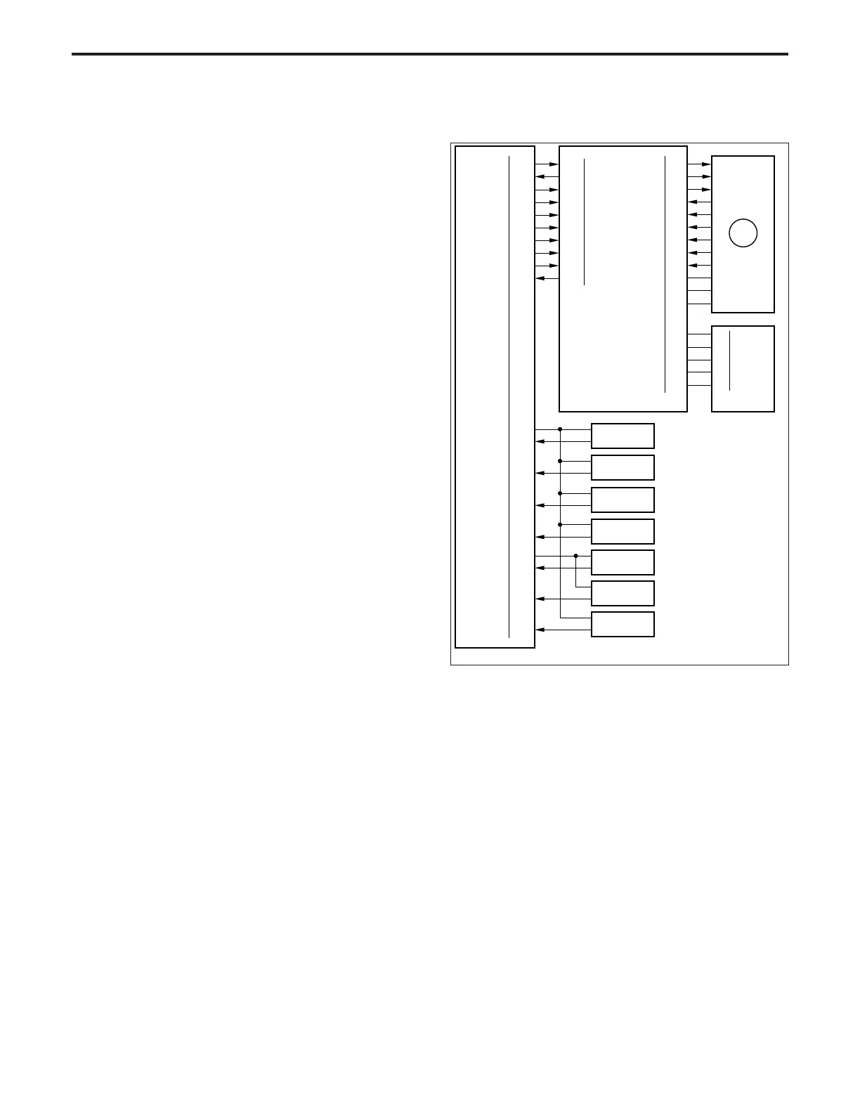
M12 (optics drive) is driven by the OPMDB (optics motor drive
board), and is controlled by the CB (control board).
Related signals are PS1 (optics overrun), PS2 (optics ADF-
AE), PS3 (shading), PS4 (paper restart), PS5 (optics return),
PS7 (optics timing) and PS8 (platen glass sensor).
1. Operation
a. Operation of M12
M12 is a 3-phase brushless DC motor which is driven using
a 3-phase bipolar method. The current flowing through the
windings is switched according to the position of the rotor
which is detected by a sensor (magnetic sensor) inside the
motor.
(10)After winding the outer wire, fix it to the wire stopper via
the outer side of pulley 1 and the V mirror pulley.
Note: There are two grooves in the wire stopper. Ensure that
the outer groove is at the rear and the inner groove at
the front.
(11)Pass the inner wire through the notch in the wire
stopper, reverse it at pulley 2, then pass it around the
inside of the V mirror pulley and also around pulley 3,
in that sequence, and attach the wire terminal to the
spring fixing plate. At this time, temporarily fix the
spring fixing plate with the set screw.
(12)Install the other wire using the same procedure.
(13)Slacken each screw that was temporarily fixed, then
install the spring on the spring fixing plate and fix each
screw once again.
READ SECTION-1